Long-lasting UPS setup with APC Smart-UPS and car batteries

Recently, I was asked to devise a system to ensure the continuous operation of the servers in a certain rack cabinet. The servers were supposed to keep working for at least 12 hours during a power outage. It also needed to be done cheaply, so buying new server-grade equipment was not an option. Naturally, a UPS came to mind, paired with large external batteries.
I started by measuring the power consumption of the whole cabinet. It turned out that it averaged about 300 W, which is not much, but the theoretical peak power (the sum of the maximum power ratings of all disks, motherboards, CPUs, etc.) was almost 1200 W. Therefore, the UPS also needed to handle this high load, however rare.
So I needed a rack-mountable UPS with at least 1200 W of peak power and an external battery connector. Because of Linux support (namely, the apcupsd daemon), I decided to limit the search to the APC brand. I purchased the APC SMART SUA2200XLI from a local company that deals in used server equipment.
The UPS
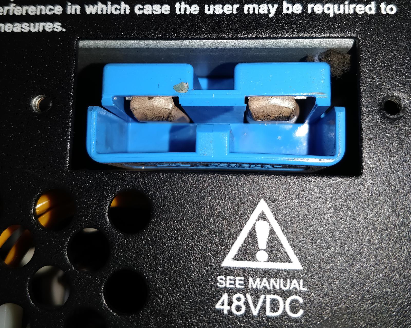
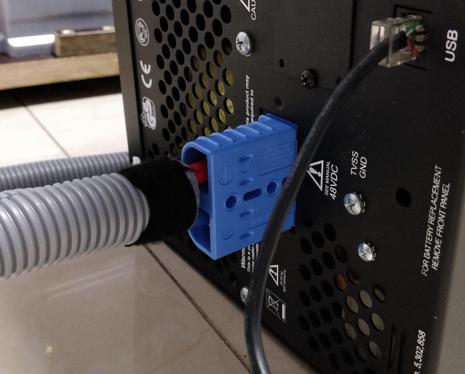
APC SMART SUA2200XLI is a rack-mountable (5U) line-interactive UPS capable of delivering almost 2 kVA of AC power. It is nominally energized by four 12 V 17 Ah RBC55 VLRA batteries connected in series and, optionally, through an external battery connector (Anderson SB120, blue—48 V). Internal batteries are not required; all power may come through the external connector. Both of these power sources seem to be connected in parallel internally. The UPS does not distinguish between external and internal power. Diagnostics and control are provided through USB, serial, and a removable networking card.
Warning
In APC UPS-es, the DE-9 serial connector has a proprietary pinout. Trying to use a standard serial cable will cause the UPS to shut down!
Since this UPS model has reached its end-of-life state, I’m providing datasheets in case they get removed from Schneider’s website:
- APC Smart-UPS XL 2200VA 230V Product datasheet
- APC Smart-UPS XL Tower/Rack-Mount 5U Uninterruptible Power Supply manual
- APC Smart-UPS XL Tower/Rack-Mount 5U External Battery Pack manual
- Installation guide Smart-UPS I/O hardware kit

Choosing lead-acid batteries
A UPS should ideally be paired with deep cycle VRLA lead-acid batteries. However, to keep the cost down, I decided to use ordinary car batteries. They are widely available and much cheaper. BTW, a great resource for reading more about various batteries is Battery University. In this application, routine discharge of the batteries is not expected to happen often, since long power outages are rare. Even during a recent major line service outage in the area, the outage lasted less than six hours. This means the batteries are not expected to lose much capacity during their lifetime, since they won’t be deeply discharged frequently.
With a load of 300 W, operating for 12 hours with 80% power conversion efficiency, the theoretical battery capacity needed is:
Therefore, I decided to use 100 Ah batteries. Searching for quality car batteries resulted in a pessimistic outlook, as only a handful of manufacturers employ the casting process to make battery plates. Most of them use punching net technology, which yields substandard results. At the time of writing, the Ukrainian manufacturer Megatex still used the casting method, so I bought four AMEGA Premium M5 100 Ah batteries.
Update Feb 2026: one of the batteries died completely, and the other three show a WEAK state on the cheap battery tester. The lifetime of three years is not great, not terrible.
Warning
Car batteries are more likely to emit hydrogen gas than AGM/VRLA batteries when overcharged. It is essential to keep the batteries in a ventilated area. The rack cabinet in this project is kept in a large corridor with natural ventilation.
Consideration of using a UPS without an external battery connector
Apart from using a UPS with a dedicated external battery connector, it is possible to connect a larger battery directly to the internal power clamps inside an ordinary UPS. My concern with this idea was that such a setup might be incapable of providing enough charging current to the large battery, resulting in an extended charging time from a fully depleted state. In extreme cases, increased self-discharge caused by cell degradation could prevent the large battery from ever being fully charged. UPS units with external battery connectors should theoretically provide a higher charging current, proportional to the number of battery packs connected. However, I haven’t confirmed whether increasing the number of battery packs actually increases the charging current in the APC Smart-UPS.
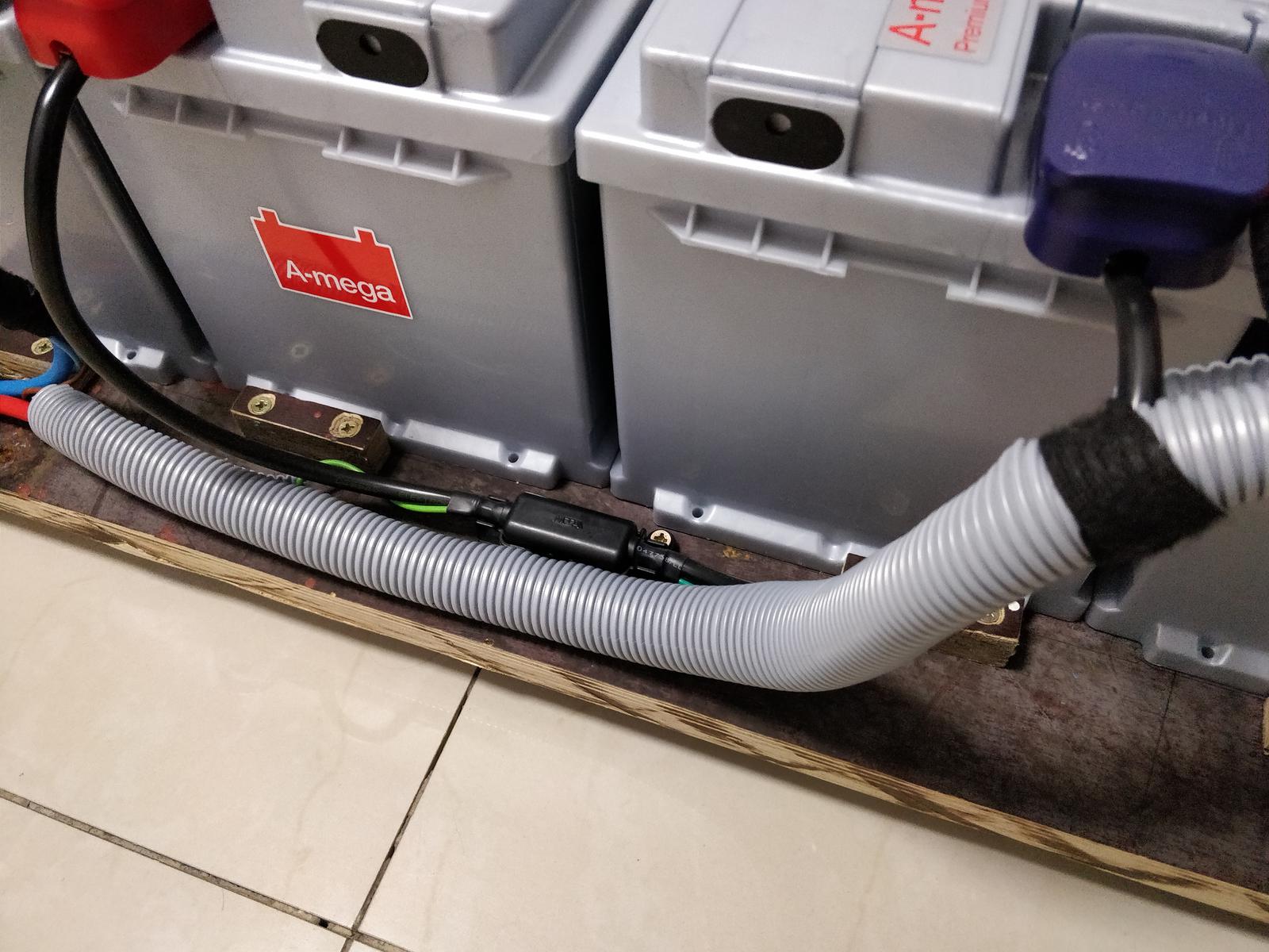
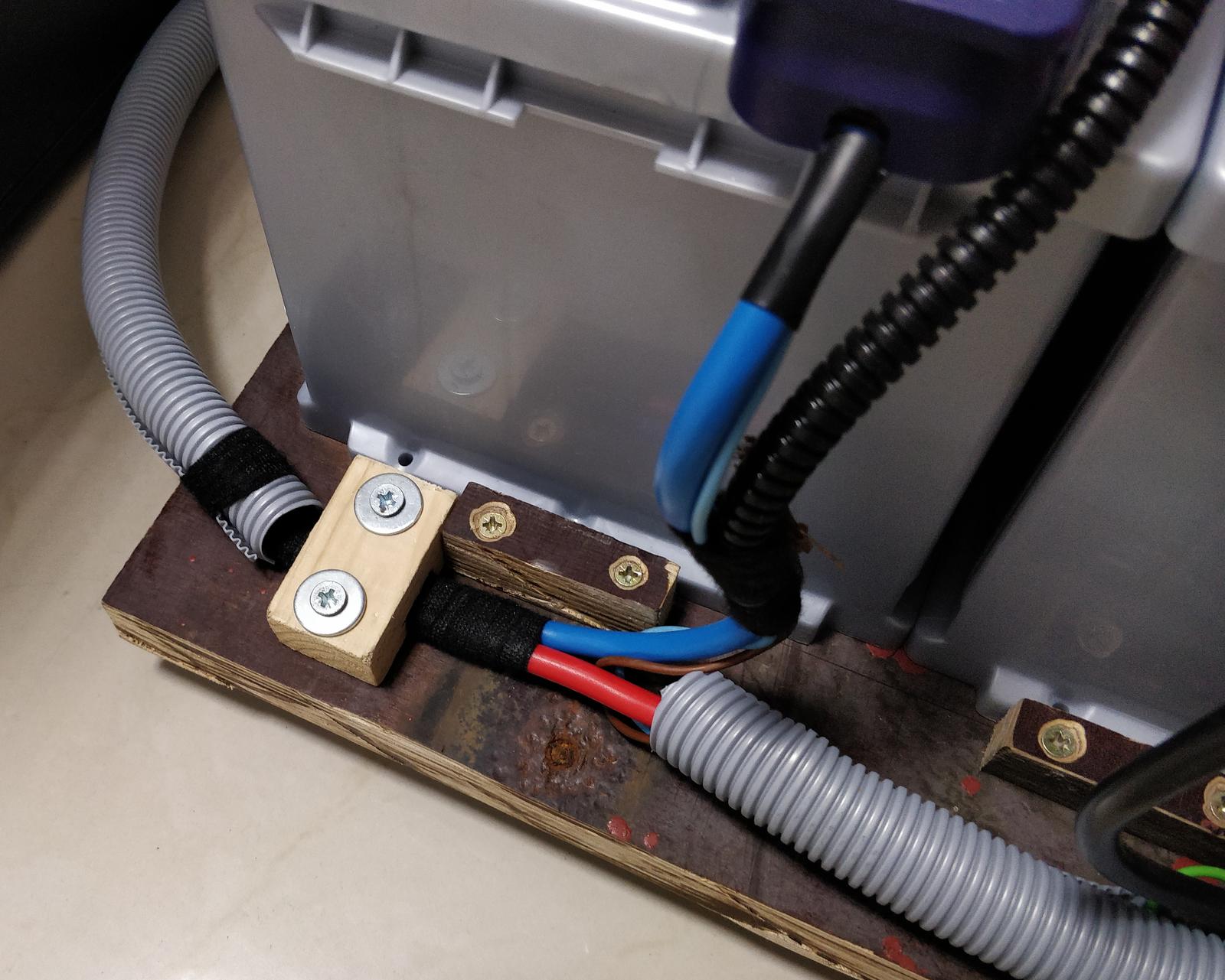
Construction
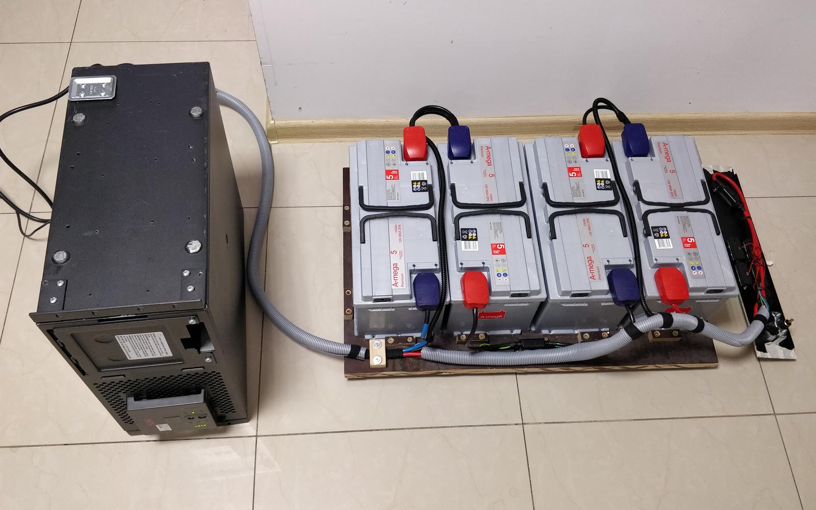

The car batteries weigh almost 100 kg, so a rugged base plate is a must. I cut 20 mm water-resistant plywood to closely match the interior of the rack cabinet. It sits at the bottom of the cabinet, supported by four caster assemblies in the corners. To make the base even stronger, I bolted a strip of plywood to the bottom. The batteries are fixed in place by several small pieces of plywood.

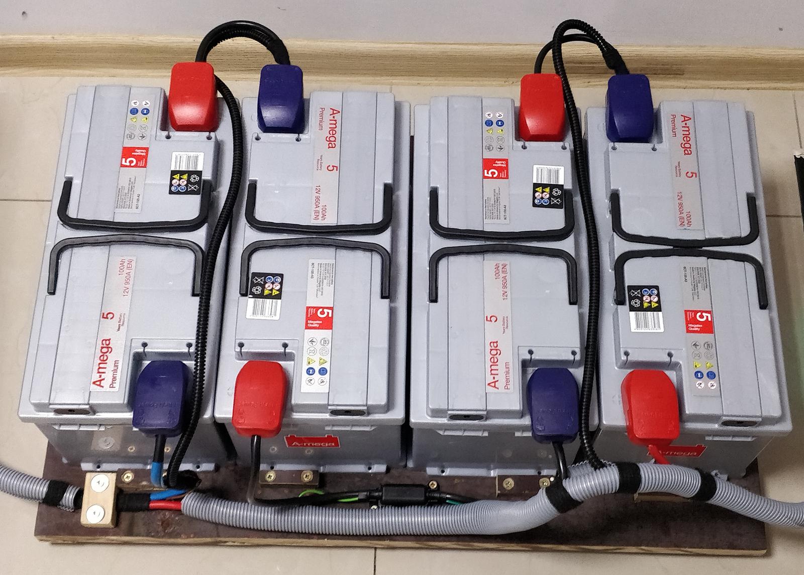

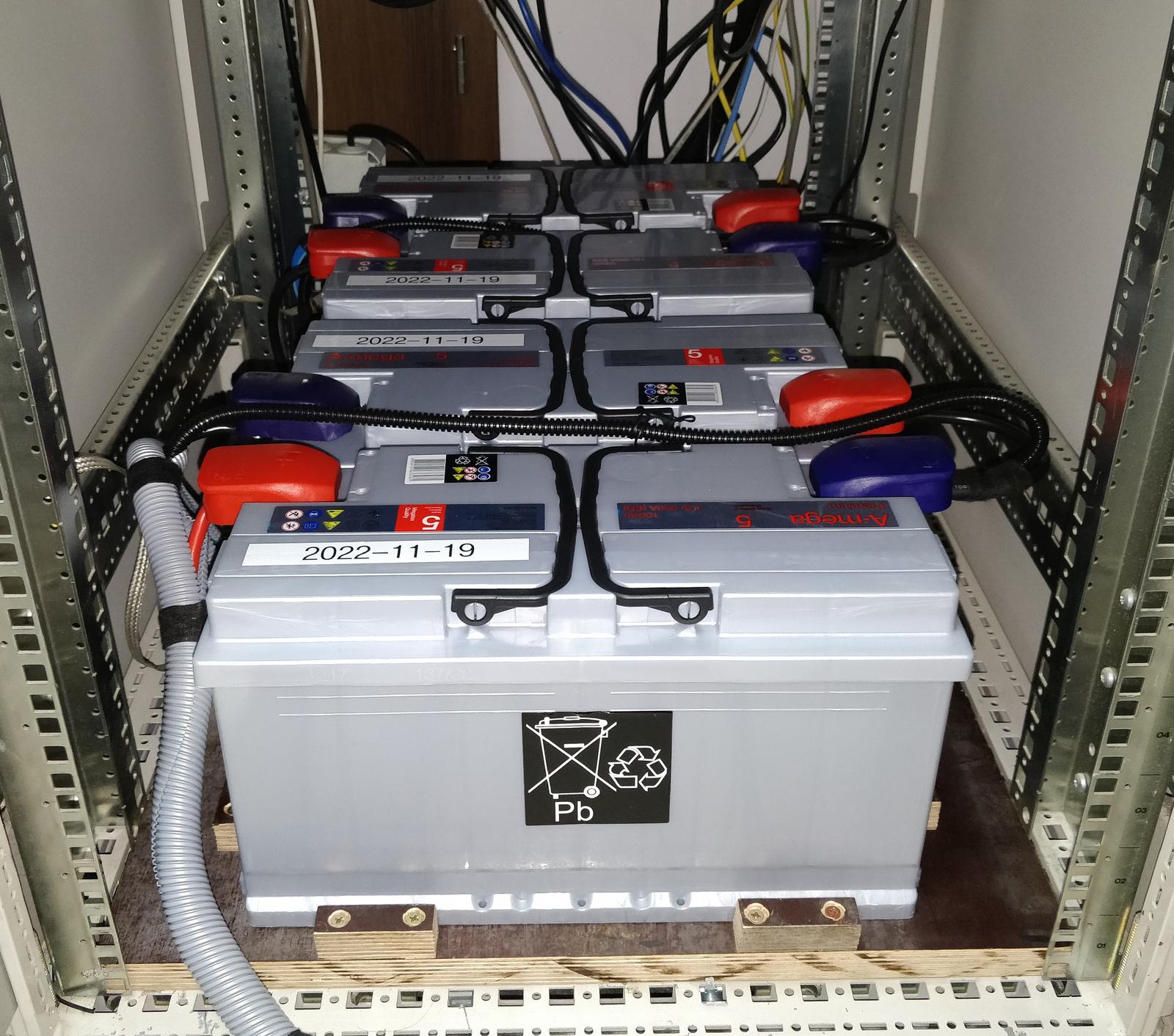
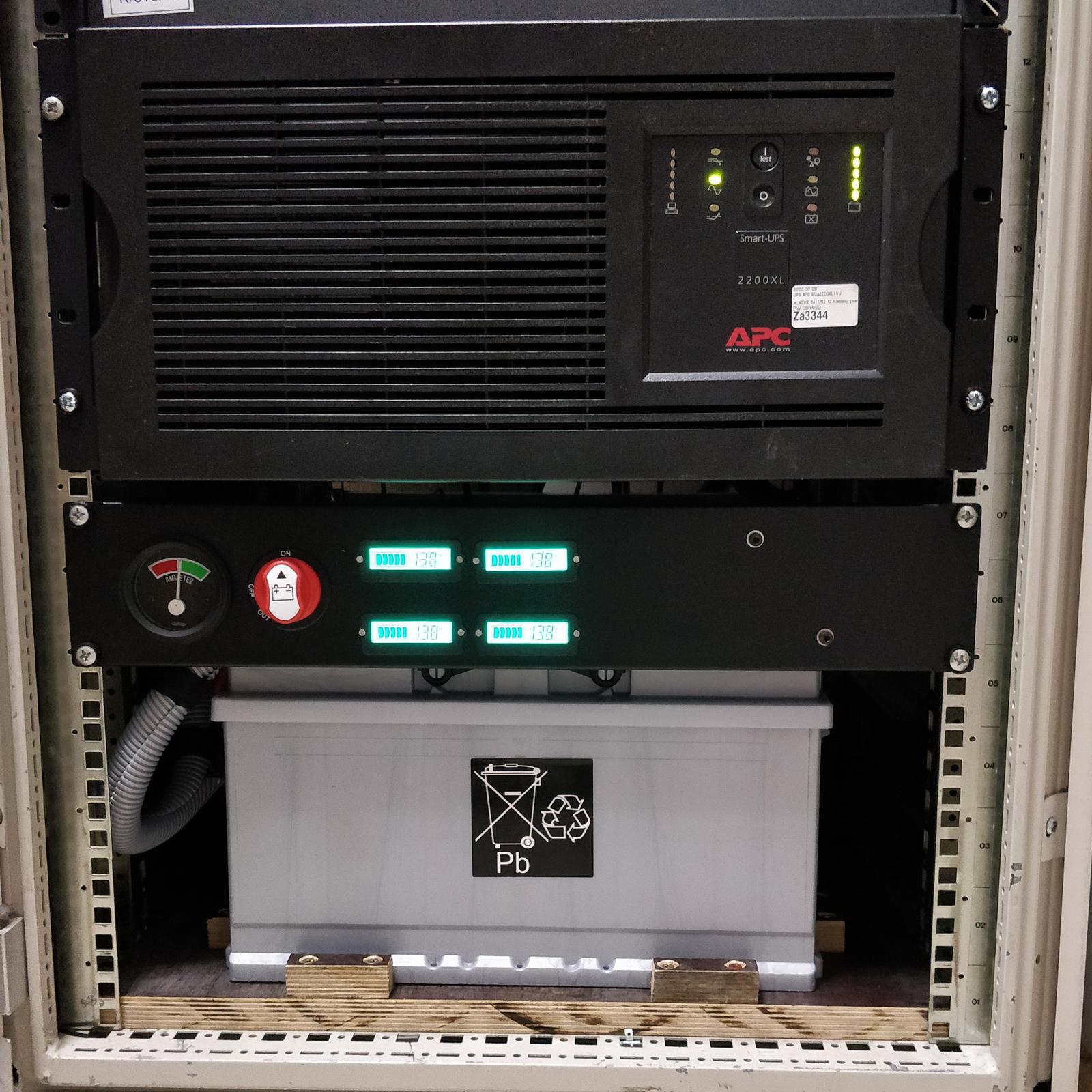
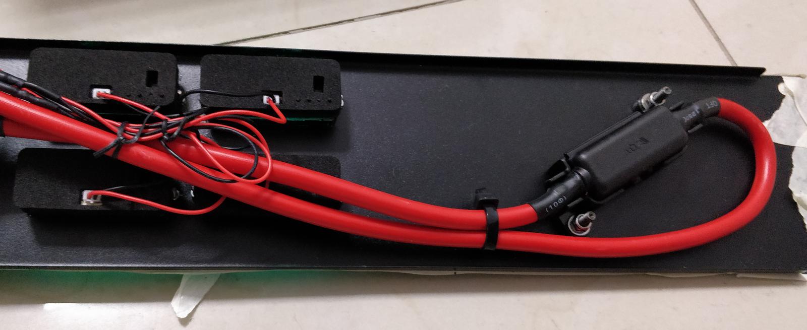
The batteries are connected in series using 16 mm2 cables and snap-on battery clamps. At the other end of the cable, an Anderson SB120 connector was crimped. To facilitate diagnostics, there’s also a front panel with measuring instruments and a cut-off switch. The front panel is a 2U blank rack panel with holes drilled for the instruments. The wiring is shown in the schematic:

Four 12 V batteries are connected in series, giving 48 V nominal. Each one has a nifty Chinese voltmeter/battery monitor LY6W attached. The meter’s current draw is normally ~5 mA, but the backlight shuts down if the voltage goes below ~10.6 V. This enables the meters to be connected at all times without fear of damaging the batteries when depleted. You can configure the meters by pressing the button on the back, as described in the manual: TH01/LY6N/LY6W battery tester.

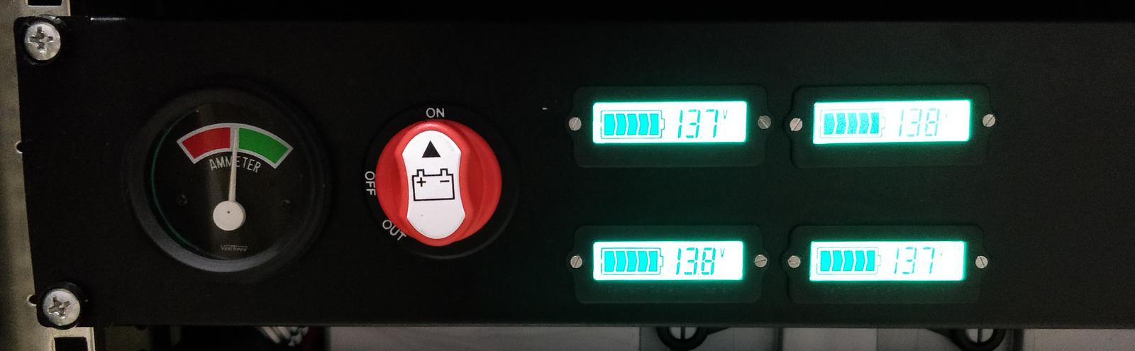
Additionally, there is a 100 A battery cutoff switch and a bidirectional 52 mm ammeter, both intended for agricultural machines. The ammeter has a range of -60 A to 60 A. Unfortunately, it lacks numerical markings on the scale.
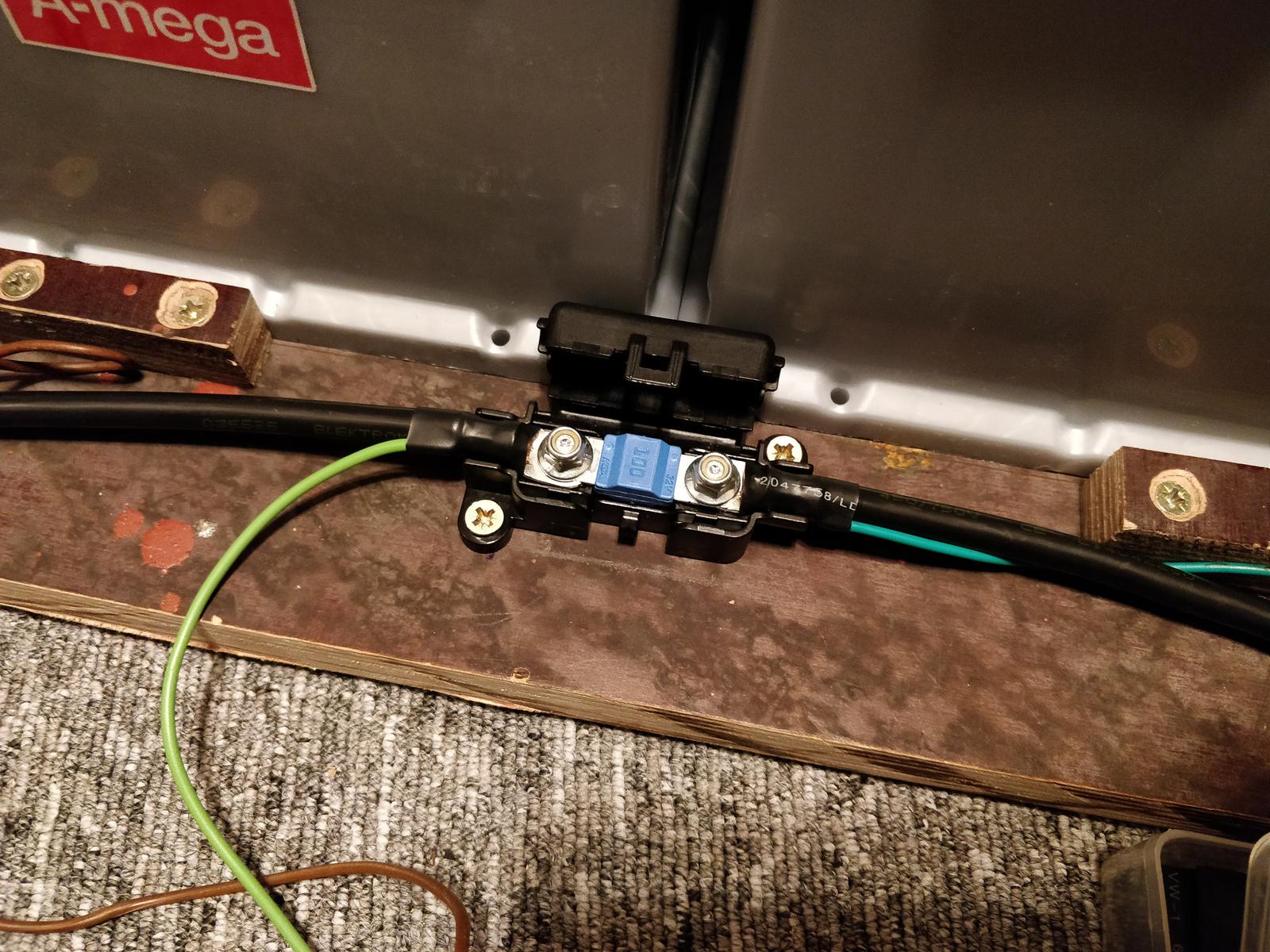
To err on the side of caution, I installed two fuses rated for 100 A, each in a MIDIVAL package, which is commonly utilized in cars and electric vehicles. The fuse shown in the photo is rated for 32 V, but the other fuse on the front panel is rated for 58 V.
Warning
It is crucial to use a fuse rated for 48 V or higher, because a low-voltage fuse may not necessarily interrupt the circuit! A sustained DC arc might prevent it from happening and potentially cause a fire!


Software and configuration
The UPS communicates with one of the Linux boxes inside the cabinet through the serial port. The same result can be achieved through the USB port, of course. The apcupsd daemon is responsible for monitoring the UPS’ state. I have set up appropriate e-mail notifications and shutdown hooks.
Note
Currently, NUT is probably more recommended than apcupsd. I use apcupsd only because my SimpleMonitor instance supports it directly.
UPS-es with external battery connectors can have multiple battery packs connected to them, to scale the capacity. With the car batteries attached, we should set the number of battery packs to a number such that the total capacity roughly matches the capacity of the car batteries. This is done so the UPS runtime prognosis matches reality more closely. I haven’t confirmed whether increasing the number of battery packs increases the charging current, though.
Considering the following facts:
- The internal battery pack is rated 17 Ah.
- One APC SUA48XLBP external battery pack is 34 Ah.
- We don’t have internal batteries.
- 100 Ah is equivalent to 2–3 external battery packs.
I have set the number of packs to 3.
Smart-UPS serial protocol was fortunately reverse-engineered in the past. All available commands are gathered here. Setting the number of battery packs can be done through a serial connection using any serial terminal software, for example:
minicom -b 2400 -D /dev/ttyS0
Alternatively, you can use the apctest command, as shown in this terminal session:
You are using a SMART cable type, so I'm entering SMART test mode
Hello, this is the apcupsd Cable Test program.
This part of apctest is for testing Smart UPSes.
Please select the function you want to perform.

1) Query the UPS for all known values
2) Perform a Battery Runtime Calibration
3) Abort Battery Calibration
4) Monitor Battery Calibration progress
5) Program EEPROM
6) Enter TTY mode communicating with UPS
Q) Quit

Select function number: 6

Enter an ESC character (or ctl-[) to exit.

>000
+OK
+NO
|>001
+OK
>002
>002
|^[
1) Query the UPS for all known values
2) Perform a Battery Runtime Calibration
3) Abort Battery Calibration
4) Monitor Battery Calibration progress
5) Program EEPROM
6) Enter TTY mode communicating with UPS
Q) Quit
One should also tweak the battery float voltage. For a nominal 48 V system, it is usually set to ~55 V (more about lead-acid battery voltages here). Many UPS-es have it set too high, which causes overcharging and excessive battery degradation over time.
The aforementioned Smart-UPS command list and Jelmer Bruijn’s article describe how to tweak the float voltage on the APC Smart-UPS. Example session:
Select function number: 6

Enter an ESC character (or ctl-[) to exit.

11PROG
B54.00
+E6
B54.54
RBYE
^[
I attached the voltmeter to the SB120 battery connector and tweaked the float voltage as described. I noticed that the voltage increased instantly when I incremented the float voltage setting, but stayed high when I tried to decrement it. So I set the value low and unplugged the UPS from the mains for a couple of seconds. That lowered the batteries’ actual voltage a bit, so I could subsequently verify the float voltage. In the end, I set it to 54.5 V.