Octoglow VFD - Fallout-inspired post-apocalyptic display

Update 2025: Major article overhaul—I updated and extended many sections to represent the current state of the Octoglow device and made new photos. I also joined the subpages into one big wall of text.
Introduction
I like post-apocalyptic themes. And Fallout games. Which is unusual since I’m not much of a gamer. There might be a special kind of pleasure in reading some post-apocalyptic SF novel while looking at your custom-made PipBoy derivative, right? Therefore, I decided to build one! For those who don’t know what PipBoy 2000 from Fallout 1&2 looks like:

Since building a real functioning PipBoy with genuine vintage components would be a monumental task, I focused on a more stationary device. In fact, I was particularly inspired by this contraption:
In-game, it is supposed to be a post-apocalyptic survival simulator proudly made for you by Vault-Tec. It has an open layout: the chassis is a steel skeleton that holds all internal components in place, and they are clearly visible from the outside. Gluing these ideas together, I came up with the following requirements:
- Vintage, dirty industrial look and feel. Naked steel, visible cables, and PCBs.
- Old-school display. I considered a CRT tube, but since driving it is quite problematic, I decided to use alphanumeric vacuum fluorescent displays instead.
- The display has to provide the following information: date, time, current weather and forecast, and other features not yet devised.
- The device should be connected to the Internet to gather data. The connection may be established using well-known Wi-Fi modules or a single-board PC.
The early concept consisted of only one PCB—the one containing the main dot-matrix display. After completing this module, I decided to create a supplementary board and mount them both on an unusually welded steel chassis made of two octagons—therefore Octoglow was chosen as the name of the device. The project has since grown considerably, but so has the fun! All design files and source code are available on GitHub, licensed under MIT.
Gallery
As the years went by, the device underwent several overhauls, so some of the photos may show older versions.


Integrations with the outside world and data collection
Have you ever experienced the following situation: you built an unusual or hackish device, had a bit of fun playing with it, and after a while, you got bored, put it in storage, and finally disassembled it? Octoglow, in order not to be an overengineered bookend, has to display some usable data. The current date and time were a no-brainer, but I needed more. Some data is collected locally; for some, I have to leverage external APIs/services. As of 2025, the device shows the following:
- Current cryptocurrency exchange rates from Coinpaprika.
- Current fiat money to PLN (Polish złoty) exchange rates from National Bank of Poland.
- Number of tasks for yesterday/today/tomorrow from Todoist.
- Failing services for my infrastructure; I use Simplemonitor to monitor them.
- Air quality from sensors in the general area from Polish Chief Inspectorate Of Environmental Protection.
- Schedule for trash collection services pickup from Poznań city website.
Moreover, the device gathers data from built-in sensors:
- temperature
- humidity
- atmospheric pressure
- indoor CO2 concentration
- background gamma radiation, to keep with the post-apocalyptic theme
Most sensors are mounted on the chassis, but outdoor weather is provided by a radio weather sensor. Background radiation data is processed like other data but is also sent to radmon.org.
All of this data is useful to me on a daily basis, so I look at the device often.
Radio weather sensors
Off-the-shelf weather station sensors emit radio packets at 433.92 MHz; these signals are subsequently received by the receiver module placed on the clock display board. I describe the protocols utilized by these sensors below:
Old weather sensor protocol - Biowin
This sensor was employed in the past; it is labeled BIOWIN BIOTERM. I reverse-engineered the protocol by connecting the receiver’s output to the PC sound card and analyzing the signal with Audacity. The process of reverse-engineering such protocols is described in detail in many articles on the web, for example here.


The sensor transmits its OOK-modulated data at 433.92 MHz. Several packets are sent every minute, less often when the battery is almost depleted. Each transmission starts with several dummy impulses, so the automatic gain control in the receiver can adjust the gain. Then, the following rules apply:
- start bit: ~9 ms of carrier wave
1data bit: ~4 ms0data bit: ~2 ms
Each single packet consists of:
- start bit
- 36 data bits
- stop bit - valued
0
and has the following structure:
| Bit | Length | Function |
|---|---|---|
| 0-3 | 4 | Always value 9. |
| 4-11 | 8 | Random number generated at power-on. |
| 12 | 1 | 0 - battery OK, 1 - weak battery. |
| 13 | 1 | 1 - transmission forced by TEST button, 0 - automatic transmission. |
| 14-15 | 2 | Address selected by switch: 00 - 1, 01 - 2, 10 - 3. |
| 16-27 | 12 | Temperature in 0.1°C. Signed, two’s complement. |
| 28-35 | 8 | Humidity in %. |
Weather sensor protocol - Fanju SP67

The new sensors, currently in action, are branded Fanju and designated SP67. I found out that someone had already reverse-engineered the protocol of these sensors. Transmission is OOK-modulated. The receiver placed on the clock board puts a demodulated signal at its output, which I recorded with a sound card. Sample message, shown in the screenshot (low state means the carrier is present):

The message starts with four pulses of carrier followed by 8 ms of carrier. This is done to adjust the gain in the receiver by AGC. Then 40 bits of data are encoded as:
- 2 ms pulse -
0 - 4 ms pulse -
1
The payload includes a checksum, which is calculated with an algorithm published on the aforementioned website. I reimplemented it in Kotlin in the octoglowd demon.
| Bit | Length | Function |
|---|---|---|
| 12 | 1 | 1 - transmission forced by TX button, 0 - automatic transmission. |
| 13 | 1 | 0 - battery OK, 1 - weak battery. |
| 16-27 | 12 | Temperature value, big endian. Formula to calculate deg C below. |
| 28-35 | 8 | Humidity in %, BCD encoded. |
| 38-39 | 2 | Channel selected by the switch: 00 - 1, 01 - 2, 10 - 3. |
temperature = (temperatureBits - 1220.0) * 1.0 / 18.0
Home Assistant and MQTT
For about a year, I have had a Home Assistant home automation system set up on my home server. I thought it would be a great idea to integrate Octoglow with it. I went with MQTT integration instead of the native Home Assistant API because I wanted to follow the loose-coupling principle. Furthermore, it would be more elegant for other not-yet-existing services to listen to MQTT topics instead of polling Home Assistant through its REST API.
Octoglow sends data from the environmental sensors to the Home Assistant (HASS) instance defined in the config. It additionally exports its controls, so it is possible to turn the magic eye on/off or simulate knob turning via the HASS dashboard or include these in automations.
While controlling the Octoglow from HASS is just a quirk made for fun and learning, collecting the sensor data is, in fact, useful. It is nice to have all the data about your home in one place.

If there’s popular demand, I might write a separate article about writing an MQTT integration in Kotlin for Home Assistant—just let me know.
Components of the Octoglow device
The device is made of several modules, the most important of which are the printed circuit boards:
-
Main display board, named
front-displayin the source code, contains a 2x20 vacuum fluorescent dot-matrix display, its driver, power supply, and rotary encoder support. -
Supplemental board, designated
clock-display; four-digit VFD display, 433 MHz receiver, two relays to drive auxiliary loads. -
Geiger counter board, containing a highly unusual circuit of Geiger-Müller counter and
driver of EM84 magic eye tube. Deliberately designed to use as many unusual components as possible. (
geiger) -
Controller board with Orange Pi Zero single-board computer as its brain, I2C
level shifter, DAC to drive analog meters and IDC connectors to connect all modules via the dedicated I2C system bus.
(
orangepi-holder)
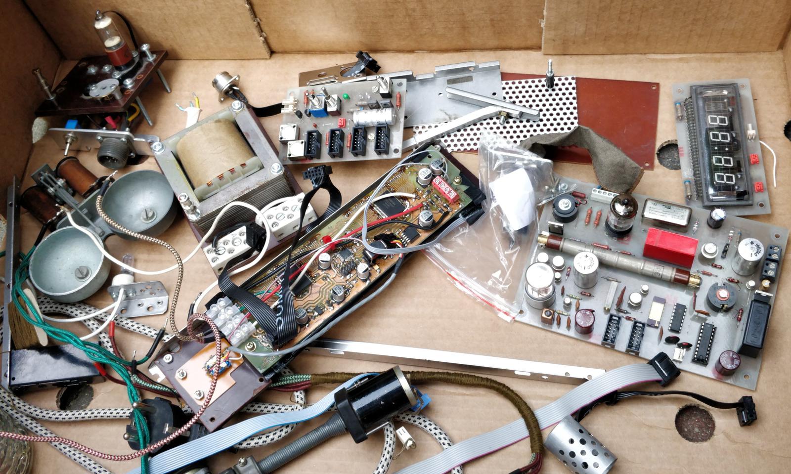
My explicit goal was to include as many vintage components as possible. Many of them have their own backstory. Despite the passage of years, I usually remember how I came into possession of them. When I do, I put notes in appropriate places in this article.
Every PCB was designed in KiCAD 5, which includes custom footprints for vintage elements. All design files and source code are available on GitHub. There is still quite a lot of space within the chassis; I may add another board in the future. If you have any ideas about it, let me know! Update 2025: schematics were updated to KiCAD 9.
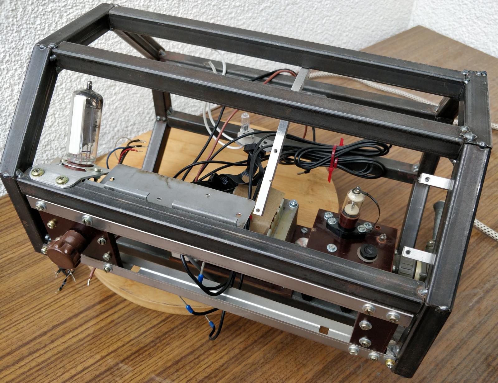
Octagonal skeleton chassis and mechanical construction
To achieve a ramshackle, but in fact aesthetic in a peculiar way, look, the chassis is made of raw steel and various scrap metal pieces. The skeleton itself is made of 15 mm raw, unpainted rectangular steel pipes. In some photos you can see that the welding is not completed—the skeleton was barely welded by me with a MIG welder just to hold the shape. At the time I didn’t have access to a TIG welding machine. After the development process was finished, the remaining job was done by a professional to achieve good-looking welds.
The dimensions are as follows:
- width: 30 cm
- overall height: 21 cm
- octagon sides made of two kinds of pieces: 8 cm, 9 cm
The skeleton is made of two parts joined by four M6 screws. You can disconnect them to gain access to the internal components.
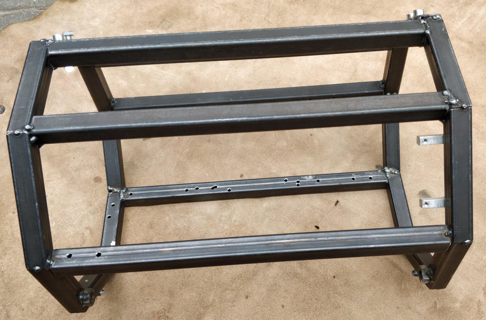


The brown box at the bottom is the upper part of the Polish MB-66 field telephone. There is some space left that might be filled by another board in the future. I’m all ears for new ideas! Elements of the front panel are Novotext sheets (in Poland, the material is called Tekstolit).
Power supply
Warning
Working with high voltage can be lethal—disconnect power before starting and verify all wiring is correct and properly isolated before powering up.
Octoglow is powered by the mains, which is 230 V 50 Hz here in Europe. The measured power consumption is about 10 watts, 15 watts with the magic eye enabled. The braided power cable from a broken clothes iron was fitted with a military-type plug.
A military-type power socket was extracted from a Radmor 3011 transceiver given to me by a ham radio operator.
I also installed a Soviet lightning arrester RB-5. It might be overkill, but the glass envelope sure does look cool, doesn’t it? There’s also a neon bulb protected by a piece of round scrap metal.
The transformer salvaged from an old medical device initially provided a single voltage: 26 V, but I wound a second center-tapped winding for powering the filaments of the VFD displays. I did it in the following manner: first, I wound ten turns and measured the output voltage. Then I calculated the required number of turns for 5 V. It was about 30. It was quite tricky to wind them without disassembling the core, but achievable indeed. It required cutting a properly long piece of magnet wire (I don’t remember the diameter, though).


Two output voltages from the modified transformer: 26 V AC and center-tapped 5 V AC, go to the circuitry located on the front PCB. 26 V AC is rectified in a diode circuit combining the Graetz full-bridge rectifier with a voltage doubler, which produce +35 V DC and +50 V DC respectively. +50 V supplies the anodes of the VFD displays both on this board and the clock board. +35 V is available on an external connector for the Geiger counter board and other future uses, and is also down-converted to +5 V by the highly popular LM2596 buck converter. +5 V is meant to be the standard supply voltage for logic circuits in the system, but some devices need +3.3 V, so an LM1117 was added to provide it as well. Capacitors on the main display board are of low value because of the lack of space on the board. Since the device’s power consumption increased, I later added an external 4700 μF capacitor and power distribution rails, so all +35 V and GND cables can be connected in one place.
Some wiring within the Octoglow is done with magnet wire insulated with a double layer of cotton. The wire comes from an ancient generator from the 1920s. This generator used to serve as an electricity source in the mill located in my father’s home village. He obtained it in some murky circumstances. This way, I’m using hundred-year-old wire in my plaything.
The center tap of the 5 V AC filament winding is connected to the +5 V DC rail to provide correct polarization of the VFD’s grids. When the VFD electrode is pulled down to GND, the grid-cathode voltage from the display’s point of view is negative, so it switches the pixels off for good. In addition, there is an NTC thermistor that limits the inrush current during startup.


I2C as system bus
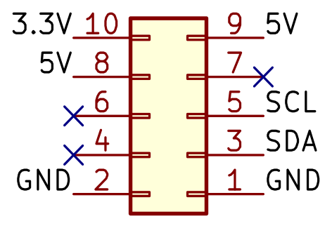
Boards and sensors are connected with 10-lane ribbon cable with IDC connectors. I chose black because it doesn’t stand out as much as a modern component compared to the more common gray ones. The bus carries I2C communication and also power: +5 V and +3.3 V for low-consumption modules. The exact pinout was inherited from one of my previous unfinished projects—hence the three unused pins. The pinout is as follows:
Communication is done via I2C, running at 100 kHz. The Orange Pi Zero on its dedicated
board acts as the bus master; all other devices are slaves. Commands and replies to/from the boards I made are verified by CRC-8-CCITT checksum to prevent working on corrupted data. Communication with the BME280 is not verified, though. The address map from i2cdetect:
     0  1  2  3  4  5  6  7  8  9  a  b  c  d  e  f
00:                         -- -- -- -- -- -- -- --
10: 10 -- -- -- 14 -- -- -- 18 -- -- -- -- -- -- --
20: -- -- -- -- -- -- -- -- -- -- -- -- -- -- -- --
30: -- -- -- -- -- -- -- -- -- -- -- -- -- -- -- --
40: -- -- -- -- -- -- -- -- 48 -- -- -- -- -- -- 4f
50: -- -- -- -- -- -- -- -- -- -- -- -- -- -- -- --
60: -- -- 62 -- -- -- -- -- -- -- -- -- -- -- -- --
70: -- -- -- -- -- -- 76 --
To simplify development, I added an external 4-pole DIN circular connector with the following pins:
- 1 - SDA
- 2 - SCL
- 3 - +5 V
- 4, shield - GND
During development, I ran the octoglowd software on my main PC and controlled the device through a USB-to-I2C converter. I detailed many ways to have I2C on PC in a separate article.


Main display board
Originally, I planned for the Octoglow to be much less complex: the idea was just a single PCB with a VFD display and ESP-12 Wi-Fi module as its brains. No post-apocalyptic themes and no retro components. Since then, the project has grown considerably and I was forced to retrofit this board because I didn’t want to make another, more elegant one. Because of this, the board has empty space for an ESP-12 module, cables soldered in various spots, and general mess.


Sourcing the VFD display
Once upon a time, I bought this display module, and since then I have always wanted to make use of it. It lay in the drawer for several years, though.
The size of the PCB is mainly determined by the dimensions of the 2x20 character dot-matrix VFD display. The original module this display came from is designated M202MD08A, manufactured by Futaba:


Most likely, its purpose was to be part of a point-of-sale system. It has an RJ45 connector with RS232 or RS485 on it, but no documentation is available. I tried to do some reverse engineering; however, the attempts were thwarted by accidentally burning the on-board microcontroller. Update 2025: someone else removed the original microcontroller and attached an AVR with a custom driver to the anode driver.
After bricking the board, I decided to desolder the VFD and design a custom board for it. First, I desoldered the IC TD62C950RF driver using a heat gun. Since the VFD is a delicate component, I took extra care during removal. I cut the PCB near the display’s pins into several pieces for easy removal before heating each piece with the heat gun. The VFD was wrapped in aluminum foil to protect it from excess heat. With the VFD desoldered, I identified the pins using the method described in my other article.
As I mentioned above, the board contained a TD62C950RF, which is a specialized VFD anode driver with 40 outputs. I desoldered it too, but fearing it might be broken, I ordered two of these chips on AliExpress. The original one was in fact fully functional; it found a new home in the clock board.
The display itself has 40 characters arranged in two lines; each character is a 5×7 dot matrix. Additionally, there is a line of triangle-shaped pixels above the upper row; they share grids with their respective characters. Overall, there are:
- 40 grids
- 5 × 7 + 1 anodes
- heater
which sums up to 76 drivable pins plus two for the filament voltage: 5 V AC.
The electrical circuit
The brain of the board is an ATmega88A microcontroller accompanied by a 16 MHz crystal and a 10-pin STK200-compatible socket for in-circuit programming. Its main task is to constantly drive the dot-matrix display. This is done by a specialized chip: TD62C950RF, a 40-output serial-to-parallel latch and high-voltage driver. It can drive loads up to 70 V, which will suit any VFD. Two of them are connected in a daisy chain, which gives 80 outputs; the display uses 76 of them. To avoid crossing traces on the board, the driver’s output numerical order does not follow the order of the electrodes on the display. This makes the firmware a bit more complicated, though.

The user interacts with the device via a rotary encoder dial, which is placed on a separate board. Parts of the schematic concerning the power supply are described in the appropriate section. There are blocks on the board that are no longer used: an ESP-12E module (not mounted) and a one-transistor amplifier for a speaker connected to the PWM output of the microcontroller.


Firmware and bus commands
The firmware was written in C++ (exceptions and dynamic allocation disabled) and compiled with avr-gcc (15.1.0 as of
2025). Because CLion is my IDE of choice, CMake was chosen instead of the more traditional make. If I had to start today, I
would probably choose PlatformIO as a build system, though. The source code root is
firmware/front-display/. I included an I2C slave library by Andreas Kaiser. The code is divided into the following modules:
noarch- The application logic. By principle, hardware-agnostic and cross-compilable under x86 as well. Covered with unit tests.avr- Hardware-dependent code, intended to be as small as possible; all hardware-agnostic logic is innoarch.font- 5×7 font definition created with GLCD software. This is the most common 5×7 font in XML format. I extended this set with Polish language characters. GLCD can generate a C/C++ header from this XML.test- Unit tests runnable under x86, written with the GTest framework.
The display works in multiplex mode. The exact frequency is not definitively set because multiplexing is done in the main loop instead of being
triggered by a hardware timer. The frequency is several hundred Hz. There is a global display buffer whose content is constantly painted on the screen.
Each character has five columns, each stored in one byte, which fits in a 5 × 40 = 200 byte buffer. Several procedures for rendering static text,
scrolling text, and also graphics modify this buffer. The text is in UTF-8 format, but only ASCII and Polish characters are supported. Any unrecognized
character is rendered as □. Sometimes there’s flickering of the pixels on the screen; this is because of the lack of double buffering. I might implement it in the future.
Overall, the firmware listens for I2C requests at address 0x14. Each command and its response has a CRC8 checksum at the start.
If the checksum doesn’t match, the request is ignored. The following requests are supported:
Get encoder state
The state of the encoder’s counter and buttons is queried by software frequently (every ~20 ms) to minimize the user interface’s latency. Request:
crc8|'1'.
Response: crc8|'1'|encoder delta|button state.
| Value | Size | Description |
|---|---|---|
| crc8 | 1 | CCITT CRC-8 sum of the whole response. |
1 |
1 | Command identifier (GET_ENCODER_STATE). |
| encoder delta | 1 | Signed integer, how many ticks since the last read. Set to zero after read. |
| button state | 1 | 1 - just pressed, 255 - just released, 0 - no change since last read. |
The encoder code was adapted from this Arduino library. It uses a combination of polling and interrupts.
Set display brightness
Request: crc8|'3'|brightness:
| Value | Size | Description |
|---|---|---|
| crc8 | 1 | CCITT CRC-8 sum of the whole request. |
3 |
1 | Command identifier (SET_BRIGHTNESS). |
| brightness | 1 | From 0 (display shutdown) to 5 (max). |
Brightness is controlled by setting the CL pin of the TD62C950RF at the proper place in the multiplexing loop code. This creates crude PWM
control. No hardware timer is used.
Response: crc8|'3'.
Write static text
Request: crc8|'4'|start|max length|text.
| Value | Size | Description |
|---|---|---|
| crc8 | 1 | CCITT CRC-8 sum of the whole request. |
4 |
1 | Command identifier. |
| start | 1 | Starting position of text. Between 0 and 39. |
| max length | 1 | Max length of the text. If the text is shorter, the remaining space is filled with spaces. |
| text | n | Zero-terminated UTF-8 text. Only ASCII and Polish characters are supported. If the text is longer than the display allows, it’s truncated. |
Static text is set by directly copying the character shapes to the pixel buffer. Response: crc8|'4'.
Write scrolling text
The device supports three slots for scrolling text, which can all be displayed simultaneously.
| Slot | Capacity |
|---|---|
| 0 | 150 |
| 1 | 70 |
| 2 | 30 |
Capacity is in bytes, so using multibyte UTF-8 characters (namely, Polish ones) will reduce the effective size. Animation speed is fixed and determined empirically to be readable but not boring to the viewer. If the text fits in the text window completely, it is displayed as static text.
Scrolling text animation works by first filling the slot buffer with a pixel rendition of the text and then copying a part of it into the display buffer. The window shifts left at each animation progression. Because of the lack of double buffering, the text sometimes flickers, but this can be considered not as a bug but a feature, because it increases the post-apocalyptic immersion.
The command: crc8|'5'|slot|start|length|zero terminated text.
| Value | Size | Description |
|---|---|---|
| crc8 | 1 | CCITT CRC-8 sum of the whole request. |
5 |
1 | Command identifier. |
| slot | 1 | Slot number. |
| start | 1 | Starting position of text. Between 0 and 39. |
| length | 1 | Length of the text window. Length + start position cannot exceed 39. |
| text | n | Zero-terminated UTF-8 text; max length depends on the slot. |
Response: crc8|'5'.
Draw graphics
Moreover, it is possible to load arbitrary data to the pixel buffer. This feature is crucial when drawing charts.
Request: crc8|'6'|start|length|sum with text|column bytes.
| Value | Size | Description |
|---|---|---|
| crc8 | 1 | CCITT CRC-8 sum of the whole request. |
6 |
1 | Command identifier. |
| start | 1 | Starting column. |
| length | 1 | Number of columns. |
| sum with text | 1 | 1 - when sum with existing content. 0 otherwise. |
| column bytes | n | Content. Youngest bit is associated with the uppermost pixel. |
Response: crc8|'6'.

Set upper bar content
The display contains an upper bar composed of triangle-shaped pixels. This makes a nice progress bar; I use it as such in the app. To set its content:
crc8|'7'|content.
| Value | Size | Description |
|---|---|---|
| crc8 | 1 | CCITT CRC-8 sum of the whole request. |
7 |
1 | Command identifier. |
| content | 4 | Content of the bar. Youngest bit is the leftmost pixel. |
Response: crc8|'7'.
Clear display
Request: crc8|'2'. Response: crc8|'2'. Sets the display content to empty. Clears all buffers.
Read end year of construction
Just after the board is powered on, it displays the credits: 2016-20xx Michał Słomkowski slomkowski.eu. To have the end year always up to
date, the octoglowd application updates this year at each start.
Request: crc8|'8'. Response: crc8|'8'|year.
| Value | Size | Description |
|---|---|---|
| crc8 | 1 | CRC-8 sum of the whole response. |
8 |
1 | Request identifier. |
| year | 1 | Byte with the last two digits of the construction year. |
Reads the end year of construction from EEPROM.
Write end year of construction
Request: crc8|'9'|year. Response: crc8|'9'.
| Value | Size | Description |
|---|---|---|
| crc8 | 1 | CRC-8 sum of the whole request. |
9 |
1 | Request identifier. |
| year | 1 | Byte with the last two digits of the construction year. |
Writes the end year of construction to EEPROM.
Rotary encoder board
For a long time, the Octoglow’s rotary encoder was a generic unbranded 6 mm one, the first I had found in my electronic component box. It soon developed a little too much play. Besides, the brown bakelite knob was rather ugly, if you ask me. I had another knob, much nicer-looking, but it had 4 mm internal diameter.
But the most annoying issue was miscounting steps, the crucial problem that troubles every embedded programmer who attempts a naive approach in the encoder’s service routines. To have it solved once and for all, I especially recommend the code from the Buxtronix website, an elegant state machine solution.
To be done with these problems, I designed a completely new mount for the encoder. The new solution has a higher-quality Bourns encoder installed on a PCB, accompanied by RC filters, as specified in its datasheet. Using a lathe, I turned a shaft to connect the 6 mm encoder to the 4 mm knob. The shaft is stabilized with a small piece of orange PCB placed just under the knob, so the play is minimal.


The Bourns PEC11H-4120F-S0020 is a standard, albeit high-quality rotary encoder: 20 pulses per turn, 20 detents. According to
the picture in its datasheet, it is a half-step encoder, but it is a full-step
encoder in reality. The detent is at the value 11, so turning clockwise generates the following pattern on its outputs (* marks
the detents):
   **          **
01 11 10 00 01 11 10 ...
The RC filters on the schematic were shamelessly copied from the datasheet. RC filtering is not required when using Buxtronix’s code, but I wanted to stay on the safe side.


Clock display board
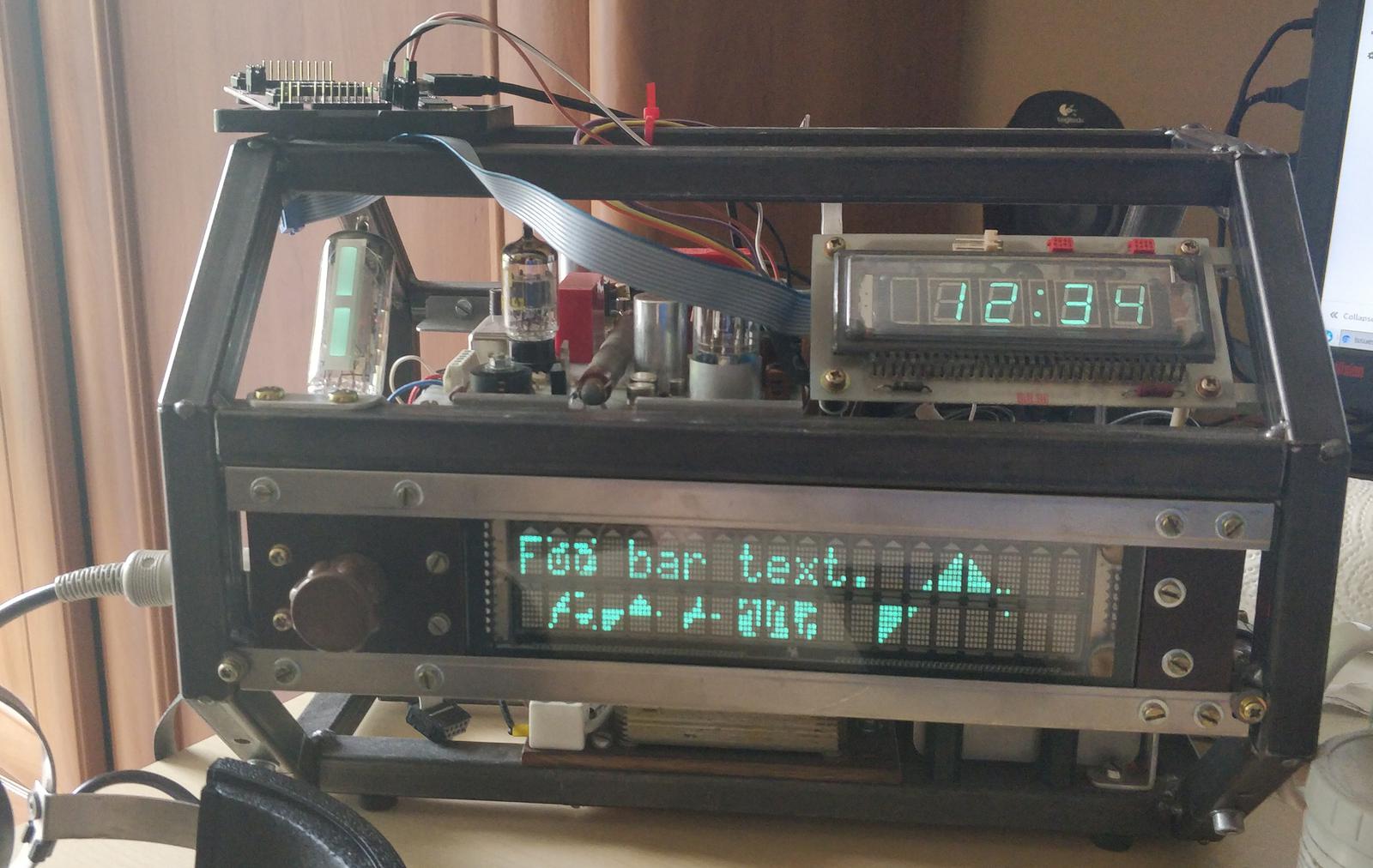
Wall time is the most important piece of information Octoglow should provide. So important that it should be visible all the time. Having this in mind, the design principles shifted to a more complicated contraption: having multiple boards and a bigger enclosure. An octagonal steel chassis was devised at this time. The new board itself features the following:
- 4-digit numerical display for current wall time.
- 433.92 MHz ASK/OOK receiver to receive temperature and humidity data from radio weather sensors.
- Two relays to drive auxiliary loads.
- Light sensor.


The circuit
The PCB’s layout was designed in KiCad; project files are located in pcb/clock-display/ in the repo. The heart of the board is
ATtiny461A microcontroller which acts as an I2C slave on the system bus. It interprets packets from the 433.92 MHz
receiver, controls the relays, and sends the appropriate content to the VFD driver. There are the following connectors on the board:
- 10-pin system bus
- 10-pin STK200 ISP header
- Female Micro-MaTch for +50 V anode voltage and filament power
- Four female Micro-MaTch’s for relays
Micro-MaTch connectors seem not to be well-known, but they were chosen because of their compactness and overall fitting look. The red color makes a good Kontrapunkt to the gray fiberglass PCB. It was important to me because the board’s front side was meant to be fully exposed to view.

The display is quite unusual because it is not multiplexed. Every anode has its own pin, and all grids are connected to each other—multiplexing is not possible in this setup. Overall, there are 30 pins to drive.
The VFD itself is salvaged from a pile of scrap electronics I found at the roadside when I was riding my bike. I took the weathered PCB home and examined the display. It was undamaged! I decided to give it a new life and purpose.
I again employed the chip TD62C950RF which successfully works in the main display board. The grid is driven by the TD62C950RF’s
output, but in the firmware, it is simply pulled high at all times. The brightness is varied by driving the CL pin with the ATtiny’s
TIMER 1 PWM output. The filament voltage is ~3 V; I leveraged the method described in my other article to find the optimal values for resistors
R8 and R10.
The original 433.92 MHz receiver module was RFM83C-433S (as seen in the schematic), but the performance was rather poor; I
later replaced it with the pin-incompatible RFM210LCF-433D-A. The antenna is made of coiled copper wire. A
spring-shaped antenna is connected through an SMA connector. The receiver’s output drives the ATtiny’s interrupt line. The protocol is described in the
section above and the decoding algorithm below.


The relay driving circuit is straightforward. One relay is dormant, the other controls the telephone bell. The bell is powered directly from the
main transformer’s 26 V AC. On the telephone line, the ringing signal is usually 25 Hz, but 50 Hz still does its job. The ringing sound is almost
indistinguishable from the classic telephone ring. The telephone bell was removed because the updated Octoglow sports two speakers with an amplifier;
it was also quite annoying, if you ask me.
Another unused thing is the pin with PWM output meant for driving analog panel meters; this job was superseded by the Orange Pi board.
The two-pin header on the front side was meant as a 1-Wire interface, but I didn’t find any use for it; it was replaced by the photoresistor. The brightness of the displays is controlled by software on the Orange Pi, influenced by sunrise and sunset times calculated for my area. A disadvantage of this approach is that when I turn the lights on at night, the displays stay quite dim. To mitigate this, I added a photoresistor in place of the inactive 1-Wire connector. It creates a voltage divider with a 33 kΩ resistor (not shown in the schematic); I measure its output voltage with the ATtiny’s internal ADC.
Firmware and bus commands
The code is located under firmware/clock-display/. It has the same principles as the main display, but no unit tests. It is quite simple;
the only not-so-trivial routine is decoding data from the receiver module. In its main loop, the software listens for commands on I2C address
0x10 and acts accordingly. The commands and replies are accompanied by a CRC-8 checksum. Commands with incorrect checksums are ignored. The
general format is:
crc8|command|[payload]
The firmware supports the following requests:
Set display content
The display has four digits and separator dots. Request format: crc8|'1'|digit 1|digit 2|digit 3|digit 4|dots.
| Value | Size | Description |
|---|---|---|
| crc8 | 1 | CCITT CRC-8 sum of the whole request. |
1 |
1 | Command byte (SET_DISPLAY_CONTENT). |
| digit 1 | 1 | ASCII-encoded digit, leftmost. |
| digit 2 | 1 | ASCII-encoded digit. |
| digit 3 | 1 | ASCII-encoded digit. |
| digit 4 | 1 | ASCII-encoded digit, rightmost. |
| dots | 1 | Bitwise OR for display dots: 0th bit = lower dot, 1st bit = upper dot. |
Reply: crc8|'1'.
Set relay state
Control the two available relays. Request format: crc8|'2'|relay1|relay2.
| Value | Size | Description |
|---|---|---|
| crc8 | 1 | CCITT CRC-8 sum of the whole request. |
2 |
1 | Command byte (SET_RELAY). |
| relay1 | 1 | Relay 1 state: 0 = off, 1 = on. |
| relay2 | 1 | Relay 2 state: 0 = off, 1 = on. |
Reply: crc8|'2'.
Set display brightness
Adjust the VFD display brightness. Request format: crc8|'3'|brightness.
| Value | Size | Description |
|---|---|---|
| crc8 | 1 | CCITT CRC-8 sum of the whole request. |
3 |
1 | Command byte (SET_BRIGHTNESS). |
| brightness | 1 | Brightness level, from 0 (display shutdown) to 5 (max). |
Reply: crc8|'3'.
Get radio weather sensor data
To get the last message packet stored in the buffer, send: crc8|'4', then read the response: crc8|'4'|flags|raw
data.
| Value | Size | Description |
|---|---|---|
| crc8 | 1 | CCITT CRC-8 sum of the whole response. |
4 |
1 | Command byte echo. |
| flags | 1 | Valid measurement = 0x2, already read = 0x4. |
| raw data | 5 | Raw data (40 bits) from weather sensor. Contains sensor channel number. Needs to be decoded. |
The core of the algorithm for the Fanju sensor is implemented in the source file src/receiver433.cpp.
The receiver module is connected to hardware interrupt INT0, and each rising edge triggers the interrupt service routine. TIMER
0 is configured as a counter; its purpose is to measure the time between subsequent interrupt calls. The interrupt service routine checks the time
elapsed since its previous execution: if it is 4 ms ± 5%, 1 is saved to the packet buffer and the buffer is shifted left.
Accordingly, when it is 2 ms ± 5%, 0 is saved. Other intervals are invalid, and the buffer is cleared in this case.
When 40 bits are loaded, the content of the buffer is copied to the spare buffer. The idea is to receive the identical packet once
again. If their contents match, the packet is assumed valid and the appropriate fields in the structure WeatherSensorState are set along with
the flag new measurement ready.
TIMER1, which is also used by the VFD routines to generate a PWM signal, has an interrupt configured to manage timeouts. When the timeout
fires, the buffer is reset. This is done to reset the state machine in case of a partially received packet.
Legacy code for the Biowin sensor is tagged in the repository as biowin-weather-sensor.
Get current light intensity
Read the current light sensor measurement. Request format: crc8|'5'.
Reply: crc8|'5'|low_byte|high_byte.
| Value | Size | Description |
|---|---|---|
| crc8 | 1 | CCITT CRC-8 sum of the whole reply. |
5 |
1 | Command byte echo. |
| low_byte | 1 | Lower 8 bits of the 16-bit measurement value. |
| high_byte | 1 | Upper 8 bits of the 16-bit measurement value. |
Values are in the range 0 to 1023. Approximate ADC values for various lighting conditions:
| When: | ADC reading: |
|---|---|
| Full sun | 5 |
| Indoors | 85 |
| Artificial light | 200 |
| Cloudy | 240 |
| Shaded | 770 |
| Lightbulb red 1200 K | 800 |
| Moderately dark | 870 |
| Completely dark | 1010 |
Indoor weather sensors combo
Octoglow, apart from looking nice, should be useful. One way of increasing its usefulness is collecting data about indoor air parameters. Currently, there are two environmental sensors installed, which collect temperature, humidity, pressure, and CO₂ levels.
The BME280 is an integrated temperature, humidity, and pressure sensor. Another sensor is the SCD40, which is a CO₂ level sensor up to 2000 ppm; in addition, it measures temperature and humidity. They are available cheaply on AliExpress mounted on small PCBs; these modules have integrated voltage stabilizers and I2C level shifters, so they can be directly connected to the 5 V system bus.
The modules were soldered together with a small electrolytic capacitor placed on the power lines, just for good measure. I encased them in a fancy cylindrical case made of RF coil shielding with holes drilled. The main purpose of the case is to shield the modern look of the modules from the viewer’s eyes, so it does not disrupt the vintage feel of the device.
The cylindrical coil shielding was extracted from some old broken vacuum tube military transceiver I bought as scrap at a hamfest.
Since temperature and humidity are available on both sensors, I calculate the average of the corresponding measurements in the software.


Geiger and magic eye board
A Fallout-inspired device should have something to do with ionizing radiation, shouldn’t it? Therefore, a genuine and functional Geiger-Müller counter, sensitive to gamma radiation. Further, it would be nice to have some visualization of the incoming gamma particles. What can be more old-school than the mysterious glow of a magic eye tube?
During the design of this board, I had an explicit goal to include as many strange and vintage components as possible. This resulted in a crazy mishmash of components whose manufacture dates span over sixty years.
The making of this board turned out to be painful. Problematic boost converters, voltage spikes roaming the board, and problems with I2C resulted in reiteration of the design on a new PCB. An additional learning curve was caused by incorporating an MSP430 microcontroller, which was completely new to me.
In the first iteration of the PCB, there was only one boost converter to supply both 230 and 400 V for both the magic eye and the Geiger tube. This proved to be unmanageable. I split it later into two separate converters. I also added a dedicated step-down converter to generate +6.3 V for the tube heaters. The result is shown in the photos:


The circuit
Since I deliberately utilized a lot of vintage components, the board is surely overengineered. One could change the design to omit many components completely, and the functionality would still be the same. However, I like it the way it is.
The schematic can be divided into the following functional blocks:
- Quartz oscillator
- System bus connectors and I2C level shifter
- MSP430G2553 microcontroller with shift register and DAC
- 400 V boost converter for the Geiger tube and pulse forming circuit
- Magic eye boost converter, featuring EAA91 as the rectifier, providing up to +230 V for the eye and -24 V for the grid driver
- Magic eye grid driver
- Filament power step-down converter

The board is supplied externally with three voltages:
- +3.3 V delivered by the system bus, powers the microcontroller
- +5 V from the system bus, powers the DAC, grid amplifier, oscillator, and I2C level shifter
- +35 V delivered by the external connector through a current-limiting light bulb, powers the high-voltage converters and filament power supply


Several resistors and capacitors have atypical values. This is just because I had them in stock. Almost all of them can be replaced by the nearest one from the E6 value series.
Crystal oscillator
The focal point of the oscillator is a beautiful quartz resonator contained in a glass envelope.
This crystal was originally mounted on a PCB which I obtained from some amateur radio enthusiast at a local hamfest. The PCB supposedly came from some obscure military equipment. It had a sticker saying 307.980 kHz on it. Imagine my surprise when it actually resonated at 5.7 MHz! The design of the oscillator reflects that, because previously I wanted to drive it in overtone mode.
The oscillator is quite sophisticated; it allows overtone mode. The inductor L2 is a so-called 7x7 radio filter,
manufactured by the Polish Polfer company in the ’80s. The transistor Q7 has a metal package. There are four capacitors between the
transistor and the MCU because the signal crosses some other routes on the PCB; it is better to use caps instead of jumpers in this situation.


Microcontroller MSP430G2553
I had owned an MSP Launchpad for a couple of years, but I hadn’t done any project featuring the MSP430 until now. Do you have several development boards in your drawer that you hardly ever played with? I do. To fight this tendency, I wanted to utilize the MSP430G2553 microcontroller, taken directly from the MSP430 Launchpad board. The Launchpad itself would serve as the external programmer.
After reading its datasheet, I felt that the microcontroller seemed quite similar to other 16-bit architectures; the highlighted advantage was low power
usage (not of use in this project, though). To flash the firmware, you need just two pins: TEST and RESET. I put them on jumper
J3 so I can connect the Launchpad to them. The MCU’s internal oscillator supports both high- and low-frequency modes; one can also feed the
chip an external clocking signal, but only at low frequency, at least according to the documentation. However, some tinkerers have successfully achieved
much higher frequencies than that, as have I. After encountering problems with low performance at 5.7 MHz, I changed the clock source to the internal 16
MHz oscillator, but the crystal still generates the clock signal for the timers.
System bus connectors and I2C level shifter
The board communicates with the Orange Pi Zero board over the system bus. I put two system bus
connectors J6 and J8 to be able to connect more devices in the future. I2C on the system bus utilizes +5 V, but the
MSP430G2553 is powered with +3.3 V. Therefore, there’s a need for voltage level shifting with transistors Q8 and Q9. I utilized
bipolar transistors merely because I had them in stock; the simpler design based on MOSFETs is used in the Orange Pi board. The bidirectional shifter is
only on the Update 2025: To solve the problems with I2C
when querying the Geiger board, I replaced the voltage divider with a MOSFET level shifter based on BS170. Apparently, the MSP430
is capable of I2C clock stretching, so a bidirectional level
shifter is required.SDA line; for SCL, it is a simple voltage divider.
Geiger tube and 400 V boost converter
The centerpiece of the board is the Soviet Geiger–Müller tube, STS-5 (СТС-5). A popular alternative is SBM-20 (СБМ-20). These Geiger tubes are sensitive enough to measure background radiation.
The tube was a leftover from my earlier project, a fairly simple USB Geiger counter, which had been published in Elektronika dla wszystkich, a Polish hobby electronics journal. The article is available online, Polish only.
The tube is supplied with +400 V from the step-up converter. The microcontroller generates a PWM signal of 40 kHz, which drives a
MOSFET gate driver MCP1402 and, subsequently, the transistor AOT8N50 (replaceable with any
other power MOSFET with a suitably high drain-source voltage). The frequency of the PWM has been tweaked in the firmware for optimal performance. The duty
cycle was railguarded to the range 2–21%. Update 2025: I replaced the MOSFETs with 12N65, because they are fully
encased in an isolated package, so touching them won’t expose the toucher to high voltage. The voltage is significant only during the short spikes, but
it’s better to be safe than sorry.
The inductor is wound by hand on a ferrite core F1001, manufactured by the aforementioned Polfer company. The same core is incorporated in the magic eye boost converter as well. Both cores have AL of 2500; the Geiger coil has 33 turns of 0.25 mm diameter magnet wire.
I remember that I extracted these cores in my early teens from a broken audio amplifier given to me by a friend.
Diode D3 is a fast silicon diode, suitable for boost converters. I forgot the exact type, though. Zener diode D1 creates 15 V
for the gate drivers. For filtering capacitor C8, I used MKF 100 nF. Update: To stabilize the output voltage,
which used to fluctuate much, I put a 4.7 µF electrolytic capacitor in parallel with the MKF. The MKFs were kept because I like their red packages.
The output voltage is divided by R9–R14 (because of the high voltage, several resistors are put in series) and measured by the
microcontroller’s ADC to close the feedback loop. In the firmware, simple P a proper PI (proportional-integral) regulator is
implemented. The ADC’s readings are averaged to lessen the influence of the omnipresent spikes. I adapted code from FastPID, a popular Arduino PID library.
Both cores were initially noisy; the noise started when the PWM duty cycle exceeded a certain threshold, perhaps because the core was going into saturation a bit. To make them quieter, I flooded them with epoxy glue. That helped substantially.
When a gamma particle strikes the Geiger tube, it creates an ionized trail which shorts the inner electrode with the
outer sheath. This generates a voltage spike on resistor R20 and the microcontroller’s input, which is, for good measure, protected with diode
D7. The СТС-5 tube datasheet recommends the series resistance to be 5–10 MΩ, but I determined that such high values wouldn’t
cause the MCU’s input to be reliably triggered. To have the initial spike exceed 3 V, I set this resistance to 1.5 MΩ (in fact, three 470
kΩ resistors in series). The proper impulse curve is demonstrated in the oscilloscope screenshot:

This follows the shape shown in the Wikipedia article. The visible voltage spikes are the interference from the boost converters, which are partially
suppressed by C35. It should be noted that a small value of the tube series resistance may lower the tube’s life expectancy. However,
background radiation intensity is orders of magnitude lower than the radiation intensities this tube is designed to withstand, so it won’t be hurt,
probably.
Magic eye step-up converter
+230 V for the anode voltage is provided by the step-up converter built in the same manner as the one for the Geiger tube. The
difference is an additional winding on the core that steals some power to generate -20 V for the grid amplifier. The high-voltage
MKF capacitor has a larger capacity than for the Geiger: 2.2 µF because the converter’s load changes; with varying stripe lengths, the
EM84 tube draws varying current. Update: I also added a 4.7 µF capacitor in parallel with the MKF to stabilize the voltage.
The MOSFET gate driver, to make things more complicated, consists of three bipolar transistors (Q2, Q3, Q5) in
metal packages instead of a dedicated IC. The rectifier is an EAA91 double diode tube.
During my childhood, I used to take pleasure in disassembling electronic devices. Once, a merry old TV repairman noticed my interest and agreed to give me some old TV sets to play with. Subsequently, he brought me a couple of old vacuum tube TVs which were no longer working. I spent many days during hot summer vacation in my grandma’s shack playing with a screwdriver and taking them apart. I still have many of the tubes from these and flyback transformers too!
According to its datasheet, the voltage between the cathode and the heater shouldn’t exceed 165 V AC, but it works flawlessly regardless. I also noticed that the vacuum tube diode is, in fact, quite fast and efficient as a boost converter rectifier. If you don’t count the power drawn by the heater, though.
The F1001 core was secured with epoxy too, because of the noise it sometimes emitted. Unfortunately, I lost the info on how many turns the eye inductor has. PWM duty cycle was limited to 2–30%. The same firmware code controls the feedback loop for both the magic eye and Geiger tubes.

Magic eye grid driver
The most prominent feature of the board is the magic eye tube or tuning indicator
itself. Below is an application schematic of the tube EM84. Other tubes like 6E1P work in the same
manner. The external signal drives the built-in triode, which subsequently drives the control electrode of the electroluminescent
indicator. On the board, R25 is the anode resistor, and R26 is the screen resistor. Putting resistor R26 in series
with the screen increases the sensitivity.

To control the indicator, the microcontroller’s built-in PWM timer would be the most reasonable choice. But I happened to own a digital-to-analog converter AD558 in a beautiful, gold-plated ceramic package. So I incorporated it into the design.
I obtained the DAC AD558 by disassembling some medical device; I don’t remember the details.
Because the pins on the microcontroller are a limited resource, I added a serial-to-parallel buffer 74HC595, U2.
Believe me, I actually searched for this particular chip in an old-school ceramic package but found nothing. CE and CS of the
AD558 are hardwired to the ground, so the IC instantly transfers the state of the inputs to the output. An eight-bit register latch U2 stores
the value sent by the MCU.


The DAC output voltage is within the 0–2.55 V range. The grid of the EM84 needs negative voltages ranging from
0 to -20 V. The op-amp U4 works as an inverting amplifier with the gain adjustable by the RV1 potentiometer. The
effective gain should be -20 / 2.55 = ~7.5. Resistor R39 protects the op-amp’s output from accidental short circuits. Varying
the voltage changes the length of the glowing stripes:
The default animation is an oscillation whose amplitude depends on the level of radioactivity. Every count event generates a tick: the stripes come together. The source code has a separate application written with the SDL library to emulate the strip on the PC; it was created to make the animation development faster.
Tube heater power supply
The device has two vacuum tubes. Naturally, they need power to heat their filaments. They consume 300 mA + 180 mA = ~500 mA at 6.3 V.
This power is provided by a step-down converter based on the LMH2596, widely used in cheap Chinese modules. Resistor
R8 limits the inrush current when the heaters are switched on; it is later shorted by the vintage reed relay K1. To be faithful
to the style, the relay is controlled by a germanium transistor of Soviet origin.
Once I was allowed to take some stuff from a liquidated workbench at my hometown’s hospital. There was some interesting medical equipment and a box with electronic components. I took these transistors because they were looking nice, having heavy metal packages.
The magic eye startup sequence begins with the heater power supply being switched on. R8 limits the inrush current. After five seconds, the
relay is activated, shorting the resistor. After 15 seconds, when the tubes are reasonably heated, the boost converter is enabled and the anode voltage
rises.
Jumper JP1 forces the heater voltage on regardless of the signal from the microcontroller. It was used during development to prevent the
occurrence of on-off cycles, which would be damaging to the tubes.
Firmware and bus commands
The firmware was written in C++ (exceptions and dynamic allocation disabled) and compiled with msp430-gcc (as of 2025,
version 9.3.1.11). Following the pattern established for the main display’s firmware, the code (root in
firmware/geiger) is divided into the following modules:
noarch- The application logic. Should be hardware-agnostic and compilable under x86 as well. Covered with unit tests.msp430- Hardware-dependent code, as small as possible.test- Unit tests compiled for the x86 platform, written with GTest framework.animationtest- SDL application for demonstrating the magic eye animation.
with the following responsibilities:
- Receiving and executing commands from I2C
- Generating PWM signals for Geiger and magic eye boost converters
- Measuring these high voltages and regulating them with a PI regulator
- Counting impulses from the Geiger tube
- Animating the magic eye
- Controlling the 6.3 V filament converter and its relay
In the main loop, the MCU listens for incoming I2C communication. Every 10 ms, the system timer ticks, and the PI regulator,
eye animation, and radiation event counter routines are called. The I2C address is 0x18. The requests are as follows:
Get device state
This request is periodically called by the application to get information about various components of the board. This data is shown on the screen. Request: crc8|'1', reply:
crc8|'1'|geiger voltage|geiger PWM|magic eye state|eye animation mode|eye voltage|eye PWM
| Value | Size | Description |
|---|---|---|
| crc8 | 1 | CCITT CRC 8 sum of the whole reply. |
1 |
1 | Command identifier. |
| geiger voltage | 2 | Raw voltage of Geiger supply voltage read from ADC, needs to be converted to volts, little-endian. |
| geiger PWM | 1 | Current PWM value for Geiger boost converter. |
| magic eye state | 1 | |
| eye animation mode | 1 | |
| eye voltage | 2 | Raw voltage for magic eye, little-endian. |
| eye PWM | 1 | Current PWM value for magic eye boost converter. |
At startup, the magic eye is disabled. One can enable or disable it by sending a 5 request. Because this is a vacuum tube that needs
heating, I devised four states:
DISABLED- Self-explanatory (0).HEATING_LIMITED- Heater voltage converter enabled; the heaters are powered through a resistor to limit the inrush current (1).HEATING_FULL- The resistor is shorted by the relay; full voltage is applied to the heaters (2), but the boost converter is disabled.RUNNING- Boost converter started; anode voltage is applied to the tubes (3).
The animation itself can be automatic (ANIMATION - 0) or manual (FIXED_VALUE - 1). In manual mode,
the DAC output value is set by the separate request.
Get Geiger counter state
The discharge pulse in the Geiger tube is illustrated in the oscilloscope screenshot
above. After the discharge itself, there’s a dead time of 200–400 µs. The firmware implements a state machine to count radiation
events. I utilized timer TA0, which also generates 40 kHz PWM, to trigger the TIMER0_A0 interrupt every 25 µs.
The input has to be high for at least 75 µs after the PORT2 interrupt. After that, there is a recovery time of 250
µs. Invalid state transitions result in an ignored count event.
For the measurement of background radiation to be accurate, the measuring interval has to be quite long; in my case: five minutes (300 seconds). It is possible to change this interval, but this feature is now unused.
Request format: crc8|'2'|, response: crc8|'2'|flags|counts in current cycle|counts in previous cycle|cycle progress|cycle
length.
| Value | Size | Description |
|---|---|---|
| crc8 | 1 | CCITT CRC 8 sum of the whole reply. |
2 |
1 | Command identifier. |
| flags | 1 | Bit 0 - new cycle has just started. Cleared after read. Bit 1 - at least one cycle has completed. |
| counts in current cycle | 2 | |
| counts in previous cycle | 2 | |
| cycle progress | 2 | In seconds |
| cycle length | 2 | In seconds, 300 by default |
Set Geiger counter configuration
The configuration, for now, is just the measurement cycle length. The current software doesn’t change it, so this command is left unused. Execution of
this command also resets all counters. Request: crc8|'3'|cycle length:
| Value | Size | Description |
|---|---|---|
| crc8 | 1 | CCITT CRC 8 sum of the whole reply. |
3 |
1 | Command identifier. |
| cycle length | 2 | Measurement cycle length in seconds. |
Reply: crc8|'3'.
Reset Geiger radiation event counters
Resets all counters. Currently unused by the software. Request: crc8|'4', reply is the same: crc8|'4'.
Set magic eye configuration
This command enables or disables the magic eye and sets its animation mode. Request: crc8|'5'|enabled|animation mode.
| Value | Size | Description |
|---|---|---|
| crc8 | 1 | CCITT CRC 8 sum of the whole reply. |
5 |
1 | Command identifier. |
| enabled | 1 | 0 or 1 |
| animation mode | 1 | Described above. |
Reply: crc8|'5'.
Set magic eye DAC value manually
Available only in FIXED_VALUE animation mode, otherwise ignored. Currently unused. Request: crc8|'6'|value.
| Value | Size | Description |
|---|---|---|
| crc8 | 1 | CCITT CRC 8 sum of the whole reply. |
6 |
1 | Command identifier. |
| value | 1 | From 0 - bars far apart to 255 - bars touching each other. |
Reply: crc8|'6'
Set display brightness
Changing brightness modifies the output voltage of the magic eye boost converter. Voltages for each brightness level:
0- 0 V1- 100 V2- 140 V3- 180 V4- 210 V5- 230 V
Changing the anode voltage affects the length of the bars on the eye, but this change doesn’t disrupt the animation much. Brightness is supported by all
the displays and the magic eye; it is calculated by the algorithm in the software. Request: crc8|'7'|brightness.
| Value | Size | Description |
|---|---|---|
| crc8 | 1 | CCITT CRC 8 sum of the whole reply. |
7 |
1 | Command identifier. |
| brightness | 1 | From 0 (boost converter shut down) to 5 (max). |
Reply: crc8|'7'.
Animation visualizer
animationtest is a simple application that uses the SDL library to visualize the magic eye animation on the PC. It imports
the appropriate code from noarch and runs it with the following effect:
The idea of the animation is the constant movement of the bars. The arrival of a gamma particle causes the bars to grow and touch momentarily. The average position of the bars depends on the average radiation level. The higher it is, the closer they are. Pressing the space key emulates a single gamma count.
Orange Pi Zero board
Finally, the brain of the Octoglow device: the board housing the single board computer, Orange Pi Zero. The reason for the very existence of this PCB is to hide the contemporary layout of the single board computer from view. Since I made the PCB anyway, I might as well put some peripherals on it.
Orange Pi Zero is one of many fruit-themed alternatives to Raspberry Pi, created by enterprising Chinese manufacturers. Its main advantage for me is integrated Wi-Fi in addition to Ethernet. Not to mention the low price. Not much computing power was required, so I went with the cheapest option.


As seen in the photos, the board holds the Orange Pi with three screws and a 2x13 goldpin header. It is powered by +5 V provided by the system bus. Speaking of which, there are four 10-pin system bus connectors, just to make the whole Octoglow future-proof. The bidirectional MOSFET level shifter converts +5 V to +3.3 V for I2C, since the Pi uses +3.3 V on its signal pins.

Moreover, there is a DAC5573, an I2C digital-to-analog converter put there to control the external analog panel
meters. It has four output channels, but only two of them are routed to the external connectors. The meters are miniature indicators of
military origin, probably from the Clansman antenna tuner/preselector. Potentiometers RV1 and RV2 are for fine-adjusting
the meters’ needle positions. Currently, the left analog gauge shows CPU utilization; the right one shows Wi-Fi link
quality.
Switch SW3 is here to disconnect the system bus from the Orange Pi and connect it to the external DIN socket instead. It
was put there to simplify the development process, as described above. Furthermore, there is the
SW2 switch, which acts as a programmatic shutdown button. Its state is observed by a Python script which calls the shutdown command.
This switch was later moved from the board to the side of the chassis.
I put two system indicators on there as well. Since I didn’t manage to find nice-looking LEDs, I used miniature light bulbs instead. They are
switched on by default; they go off only when the respective GPIO is set as output and then set to 0. When the boot sequence starts, they are
both on. After the Armbian boot sequence is complete, one light goes off. Next, after the octoglowd demon launches, the other one goes off.

Speakers
To compensate for the removal of the telephone bell, I installed laptop speakers and a small stereo class-D amplifier module. The speakers are hidden behind pieces of a perforated aluminum sheet. The amplifier is powered by +5 V and driven by the audio outputs from the Pi. I had a plan to add a microphone and implement support for voice commands to Home Assistant, but for now, the speakers are unused.

Software
The Pi has a 16 GB MicroSD card with Armbian installed. It is connected to the home network via Wi-Fi. The central application that controls the whole device is named octoglowd, described in detail in the following section.
Software stack on the Orange Pi Zero
As of 2025, Armbian version 25.8.1 bookworm is installed. Installation
is straightforward, as described on the Armbian website. With the armbian-config tool, I updated the board’s internal firmware and also
enabled GPIO and I2C 0. The following packages were installed; some are required, some are just for convenience:
apt install powertop openjdk-17-jre-headless supervisor most multitail pydf mtr htop vim iputils-ping btop wavemon git ufw i2c-tools screen
I created a separate, non-privileged user for the octoglowd demon:
adduser octoglow
gpasswd -a octoglow i2c
Furthermore, I added my .bashrc file which I usually put everywhere.
The octoglowd demon is a JVM application; to have it run at startup, I use the process controller Supervisor. It starts and monitors the application, restarting it in case of a crash. I use it regularly in a lot of
deployments; it seems to me much less complicated than systemd. The Python script software/running-proc-gpio-eventlistener.py listens
to Supervisor events and drives the light bulb in accordance with the state of the octoglowd application. When it is down, the light goes on.
So, when everything is in order, both light bulbs are dark. The config:
[program:octoglowd]
command=java -Xms16m -Xmx64m -XX:MaxMetaspaceSize=32m -XX:+UseSerialGC -XX:-TieredCompilation -XX:+ExitOnOutOfMemoryError -Djava.awt.headless=true -jar octoglowd.jar

directory=/home/octoglow/octoglowd
user=octoglow
autostart=true
startsecs=8
stopwaitsecs=6

stdout_logfile=/var/log/octoglowd/console.log
stdout_logfile_maxbytes=10MB
stdout_logfile_backups=10
redirect_stderr=true
I limit the JVM heap size to 64 MB and set various JVM options to limit the memory footprint and CPU consumption. Stdout logs are saved to
/var/log; this directory is mounted as a ramdisk in Armbian. That is to reduce the wear of the MicroSD card.
There is another Python script: software/reset-button-handler.sh; it constantly monitors the GPIO associated with the shutdown button. If
it detects state 0, it calls shutdown -h now. This is done to safely shut down the Linux system without the need to log into it
via SSH.
Adjusting I2C frequency
By default, the I2C frequency is 100 kHz; however, I was encountering read errors and bus hangups, probably caused by the interference
generated by the Geiger and magic eye boost converters. To fix it, I decreased the I2C frequency to 40 kHz, which solved the problem.
Update 2025: Fixing the I2C level shifter on the Geiger board eliminated this problem. I leave the description of changing the I2C frequency here.
To change the I2C frequency of the Orange Pi Zero in Armbian, you have to recompile the device tree (DTB) file.
These files are located in /boot/dtb. For Orange Pi Zero, the file is named sun8i-h2-plus-orangepi-zero.dtb. Decompile it:
dtc -I dtb -O dts sun8i-h2-plus-orangepi-zero.dtb -o sun8i-h2-plus-orangepi-zero.dts
Look for the I2C-0 entry: i2c@01c2ac00 in the dts file; it should look more or less like this:
i2c@1c2ac00 {
    compatible = "allwinner,sun6i-a31-i2c";
    reg = <0x1c2ac00 0x400>;
    interrupts = <0x0 0x6 0x4>;
    clocks = <0x3 0x3b>;
    resets = <0x3 0x2e>;
    pinctrl-names = "default";
    pinctrl-0 = <0x1d>;
    status = "disabled";
    #address-cells = <0x1>;
    #size-cells = <0x0>;
    phandle = <0x5c>;
};
Add an entry that sets the I2C frequency to 40 kHz in hexadecimal format:
clock-frequency = <0x9c40>;
Compile the dts file and reboot the Orange Pi Zero:
dtc -I dts -O dtb sun8i-h2-plus-orangepi-zero.dts -o sun8i-h2-plus-orangepi-zero.dtb
Octoglow demon
octoglowd (software/octoglowd) is a JVM application written in Kotlin. I made heavy use of coroutines, the Kotlin approach to concurrent programming. The task of writing this app provided
me with a nice opportunity to learn them.
It should be noted that this app is a second attempt to write the Octoglow demon. The previous one was done in 2018 in the Rust language, but I
suffered from a steep learning curve and a still-developing ecosystem. Async IO was quite immature at that time. This abandoned code is archived in the
octoglowd-rust branch in the repository.
I wanted this application to be lightweight and snappy on a low-performance SBC, so I avoided reflection-based frameworks. The raw fat JAR weighs about 12 MB, but the last step of the Gradle build is the Proguard shrinker, which generates a 6.6 MB final JAR. Some notable libraries leveraged by the new Kotlin demon:
- linux-i2c.java library — for accessing I2C devices on Linux.
- SQLDelight — generates typesafe Kotlin APIs from SQL statements and wraps the SQLite driver.
- kotlinx-serialization — for JSON serialization, doesn’t use reflection.
- Ktor — HTTP client with CIO engine, coroutine-native.
- ktor-mqtt — MQTT 5 client implementation.
- jsoup — HTML parser library.
- tinylog — lightweight logging framework with SLF4J bridge.
The architecture is all about standalone workers implementing the Demon interface. Each demon has a poll() method and an
interval at which it should be polled. Polling is done by an ordinary loop and suspendable delay() function.
Some important demons:
-
RealTimeClockDemon— called each second, draws the current time on the clock display. AnalogGaugeDemon— periodically checks the CPU usage and sets the analog meter’s needle position.-
FrontDisplayDemon— the most important demon, polls the encoder dial and draws the content of the main display.
Two message queues: CommandBus and DataSnapshotBus, are for communication between demons and are implemented with SharedFlows. Data
snapshots are all events like new pressure measurement, desired brightness changed, new piece of data from external API, etc.
Each kind of event is implemented as a separate DTO. The command bus is for user requests, which come from the encoder (like button pressed) or
MQTT (like enable magic eye).
Demons of type DataHarvester collect data from device sensors and external APIs and emit them to the data snapshot bus. They were detailed
in the chapter above.
Some kinds of data snapshots are published to MQTT, so Home Assistant can display them. Additionally, some are stored in the SQLite database. The database is subsequently queried for aggregate data to create charts, which are drawn by the views. MQTT support was implemented in 2025; previously, there was only SQLite. I used to have a plan to do some statistics or charts with the gathered data and present them over a website interface, but now Home Assistant does it perfectly.
Naturally, there is code for communicating with each I2C device. The Linux kernel I2C API is wrapped by the
linux-i2c.java library. Each sensor and board has their commands (described in sections about bus commands) implemented in their class, which
extends the I2CDevice class. They calculate CRC8 and have a retry mechanism in case of failure. The code is suspendable (in coroutines’
sense); IO is executed with Dispatchers.IO.
Front display demon
FrontDisplayDemon is the most complicated demon because it manages the user interface. It is based on the concept of
views. Each view is concerned with a specific area of interest like outdoor weather, exchange rates, etc. This can combine data from one
or several sensors or APIs. The view listens to the data snapshot bus; if something interesting happens, it updates its internal state. Two types of
internal state are defined: status and instant.
Status is updated by the arrival of new data snapshots. New data usually arrives every few minutes. If the status is recalculated, the display demon chooses the view as the next view to be shown.
Instant is polled only if the view is displayed on the screen. It is to show some diagnostic ephemeral data, like current on-board voltages of the Geiger board. It is not updated by the arriving data snapshots but is polled separately. The polling interval is usually in the order of hundreds of milliseconds. This data is not stored anywhere permanently.
The user can cycle between the views by turning the knob or calling dial turned events via MQTT/Home Assistant. If there’s no input from the
user for a prolonged time, the views are cycled automatically at a predefined interval. Each view can also define its own menu. One enters
it by pressing the knob. For example, GeigerView has a menu to enable or disable the magic eye. Additionally, there is a menu to choose a
display brightness level: 1–5 or AUTO.
As of 2025, there are twelve views implemented. Some are shown below:


Summing up
This Octoglow project and its article on this fine website are something I come back to semi-regularly to play with, overhaul, and modify. Major revisions were done in 2019, 2023, and recently, in 2025. There’s still some space within the chassis. I would gladly hear any suggestions, for example, what other boards or modules can be added there to further the post-apocalyptic immersion.
My own ideas are:
- Adding a vintage microphone and local (non-cloud) voice recognition integrated with home automation (namely Home Assistant)
- Adding a lightbulb socket on the backside so that in the evening the device provides background light and looks great
I hope you had fun reading this somewhat long description. Maybe you have built something similar? Let me know!