Installation of Webasto Thermo Top Evo heater in Mercedes-Benz W124

Winter has not yet kicked in for good in Poland, but it is a good idea to be prepared for it. Speaking of preparation, I decided to install a parking heater called Webasto in my ‘94 Mercedes-Benz W124 diesel. These cars used to come with a parking heater DBW46/BBW46 as an option, but these are hard to obtain and quite complicated. To make things worse, spare parts are no longer available. I chose to use a much more modern and compact solution - Webasto Thermo Top Evo. I wanted to keep the interior of the car original, so I used a genuine clock/timer from the W124, as shown in the cover photo.
The installation process for a generic vehicle is described in the official installation manual, so there’s no need to repeat it here. I’ll provide insights about the installation specifically in my car. What differentiates my setup from the one described in the manual:
- Instead of a dedicated W-BUS digital timer, like 1533, I used a so-called analog timer accompanied by a W-BUS emulator.
- I utilized the existing circulation pump, which is a standard part of the interior heating, rather than installing an additional one. This required a simple electronic circuit to fool the heater.
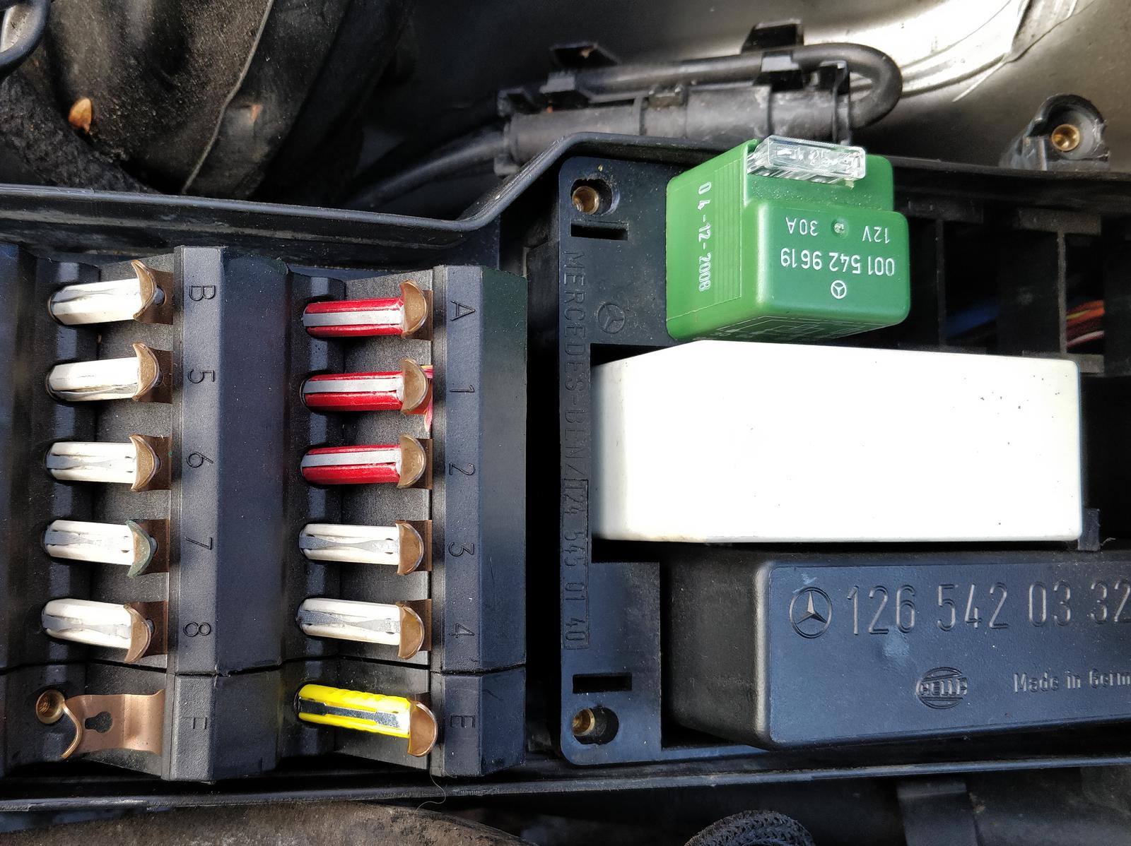
- I made use of the existing space in the fusebox and added an MB-specific relay to control the blower.
To clarify things: when I write Webasto, I mean the whole parking heater installation. When I write heater, it means just the rectangular module, which is the central element of the system.
To begin with, all the relevant documents I have found are gathered here:
- Catalogue entry
- Installation instructions
- Workshop manual
- Marine installation
- Instruction of Thermo Top Test diagnostic software
Additional references:
Diagnostic interface RS232 - W-BUS
Thermo Top Evo utilizes the so-called W-BUS (Webasto Bus), which is, in fact, the K-line, a single line of two (K and L), defined in ISO 9141-2 and ISO 14230-4 (On-board diagnostics standards). It is a low-speed bus, using +12 V and 0 V as high and low states, respectively.

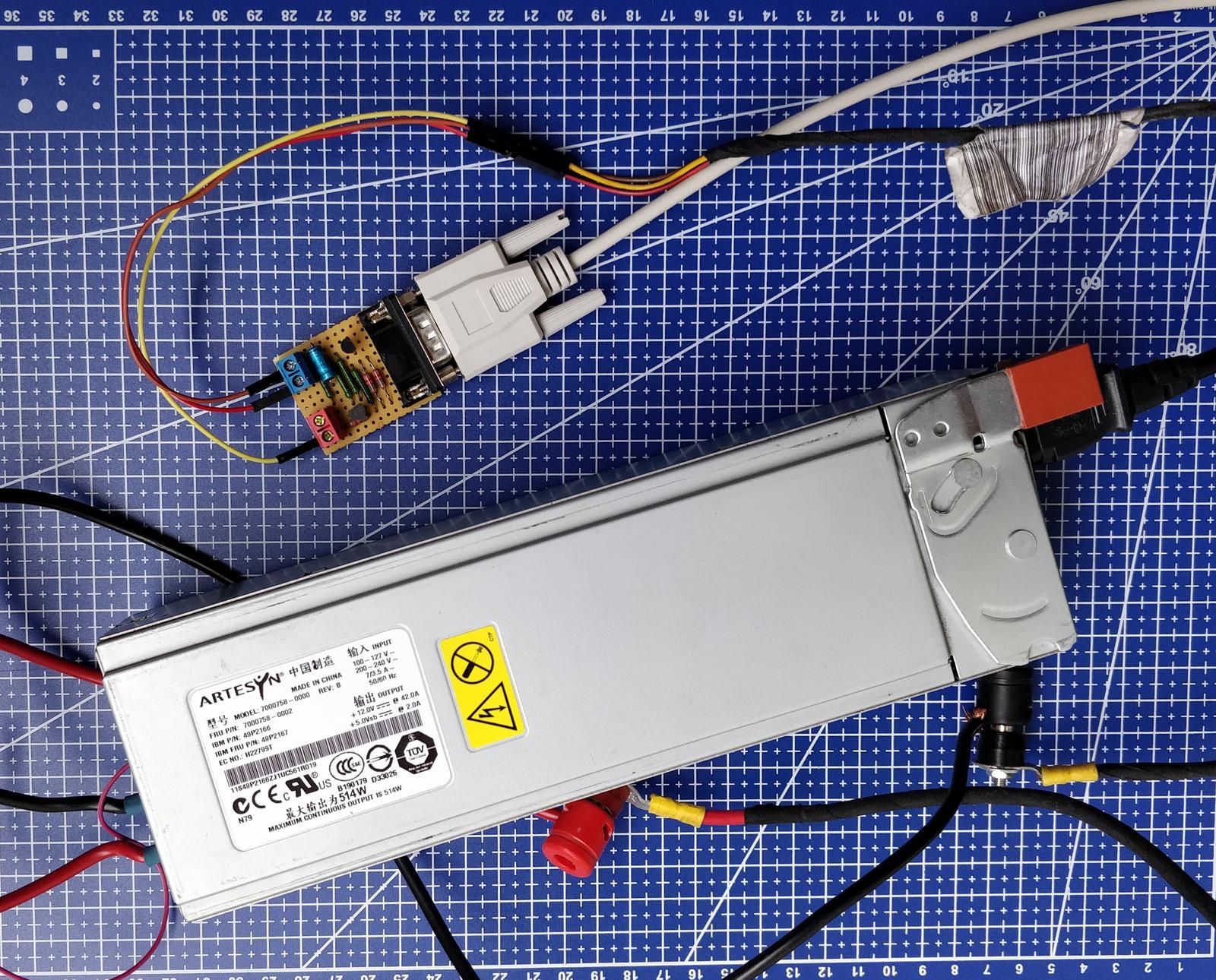
I know it’s quite old-fashioned, but I’m a bit nostalgic about RS232. The circuit is straightforward; I’ve assembled it on a piece of universal board. You can use almost all low-power NPN and PNP transistors. I myself used a male DB9 connector and a null modem cable. If you replace it with a female connector, you’ll need to swap the RXD and TXD pins. The circuit also works with USB-serial converters without issues.
Instead of building a dedicated RS232 converter, you can probably get away with using the OBD-II interface. K-line is on pin 7. It’s important that the device presents itself to the PC as a serial device, which is required by the Webasto Thermo Test software.
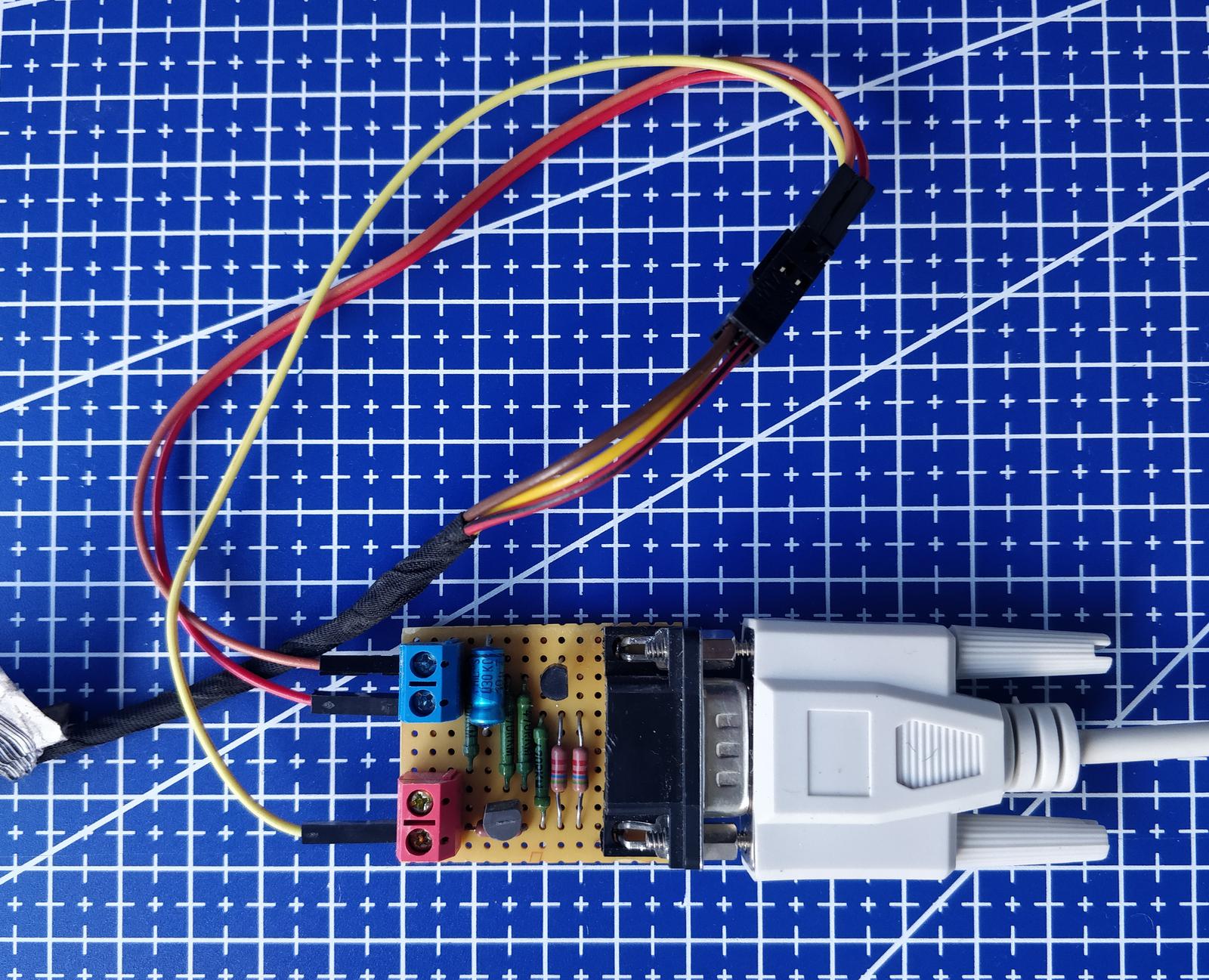
The W-BUS is available at the timer connector, which is normally connected to the 1530 or 1533 timer. The pinout is as follows:
| Color: | Function: |
|---|---|
| red | +12 V |
| brown | ground |
| yellow | W-BUS |
Testing the heater before the installation
To test my Webasto before the installation, I set up an ad-hoc circuit consisting of the heater module, fuel pump, circulation pump, water tank and some rubber coolant hoses. The tank was filled with demineralized water; the fuel line was placed into a small canister of diesel. 12 V power was provided by a server computer power supply. Probably any ATX power supply will work as well; about 20 A is needed during the startup sequence.
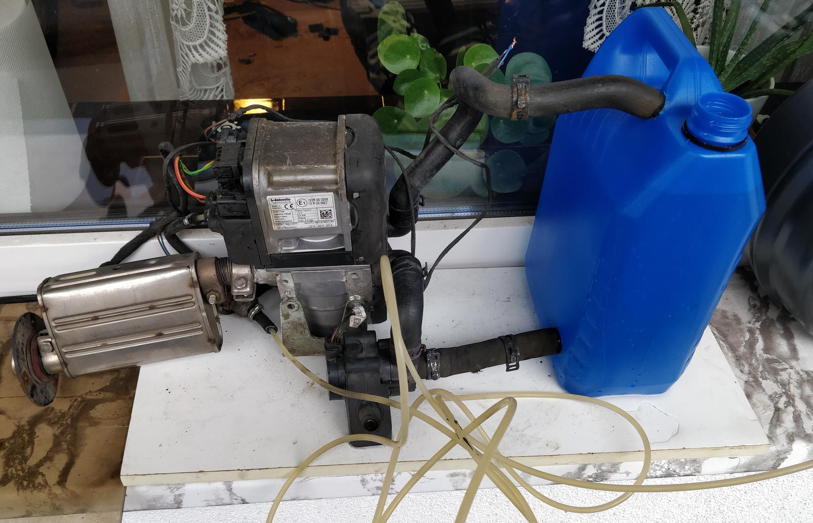
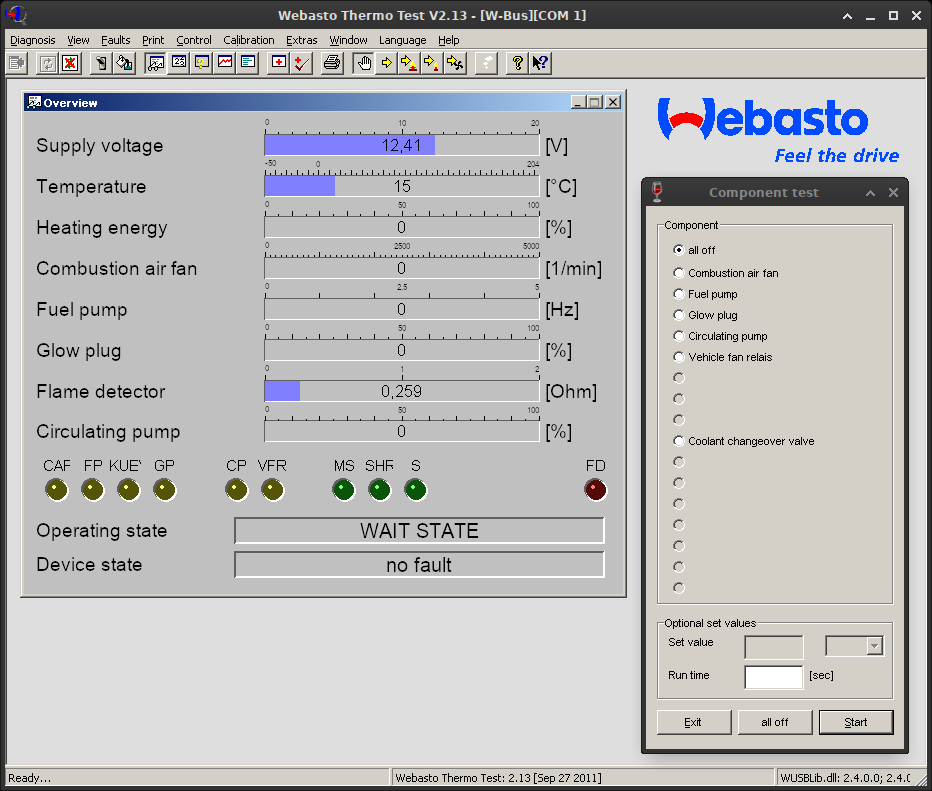
The diagnostic software for the heater is Webasto Thermo Test. Versions 2.x are freely available on the Internet, and the software works well under Linux with Wine. Before starting, you need to map the serial port to be visible under Wine.
Before running the test, it’s recommended to test each component of the system separately. You should also prime the fuel line to ensure it’s filled with fuel. Here’s a screenshot of WTT when idling:
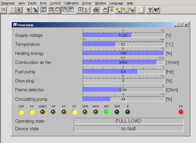
Once you start the heating sequence, the circulation pump turns on, and you should begin hearing the clicks of the fuel pump after a while. The status of each subsystem is visible in the Overview window. Eventually, it should resemble the screenshot below. Water heats up quite quickly, so it’s advisable to stop the heating sequence after a while.
Mechanical installation
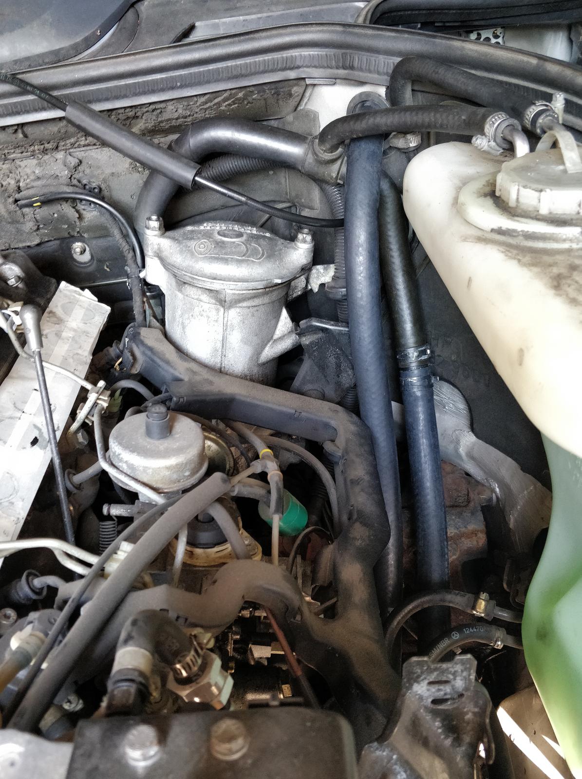
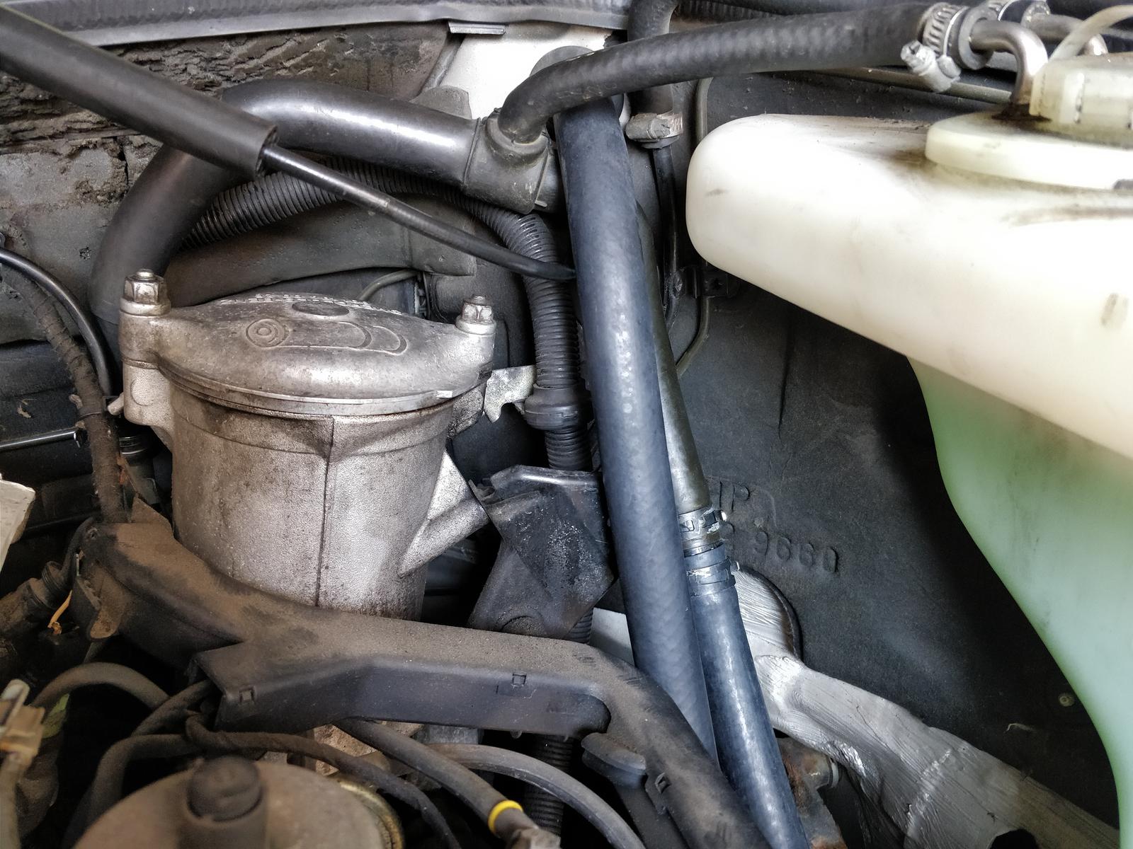
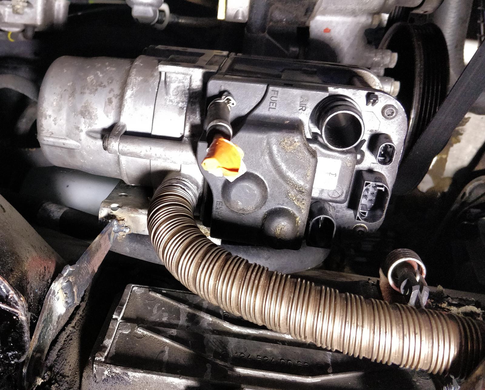
Since the car lacks air conditioning, there is ample free space under the power steering pump. This happens to be the only viable location I could think of to install the heater. I’m uncertain whether there would be enough space if an A/C compressor were present. The only other conceivable locations for the heater installation are the empty spaces between the wheel well and the front bumper on both sides. However, this would necessitate a much more complicated coolant hose installation.
The heater was positioned as high as possible to create room for its muffler below it. The exhaust must follow a straight line, with a slight tilt downward towards the outlet. This design choice is crucial to prevent condensing water from lingering in the lines. These specific issues are outlined in the manual.

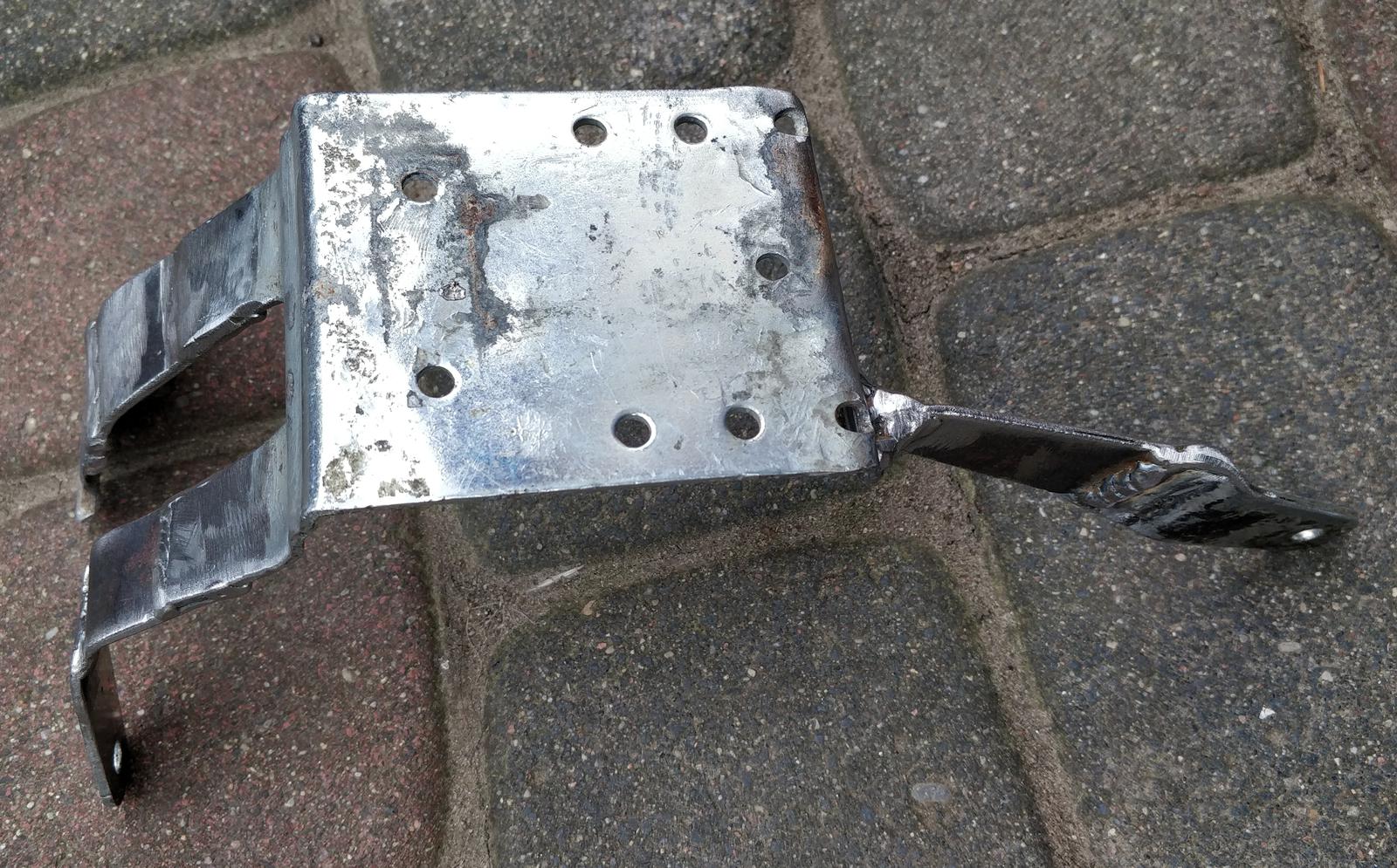
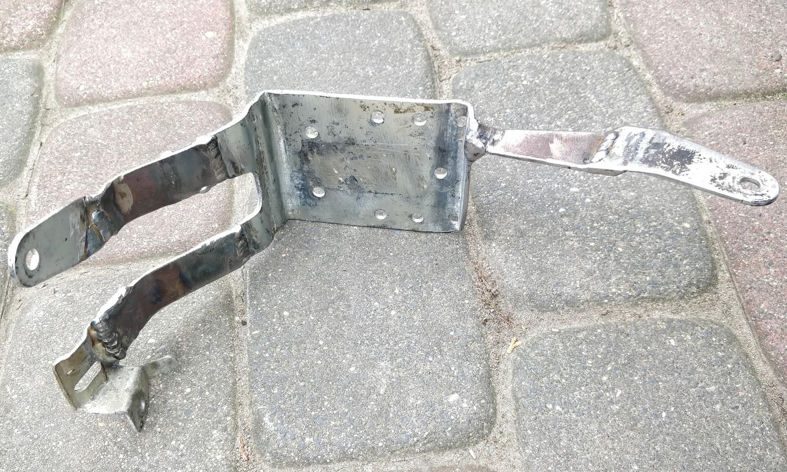
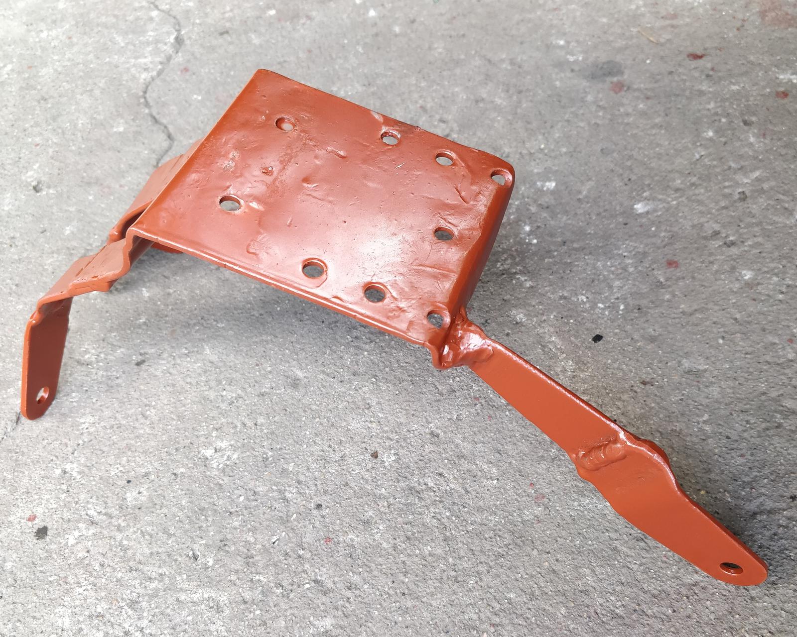
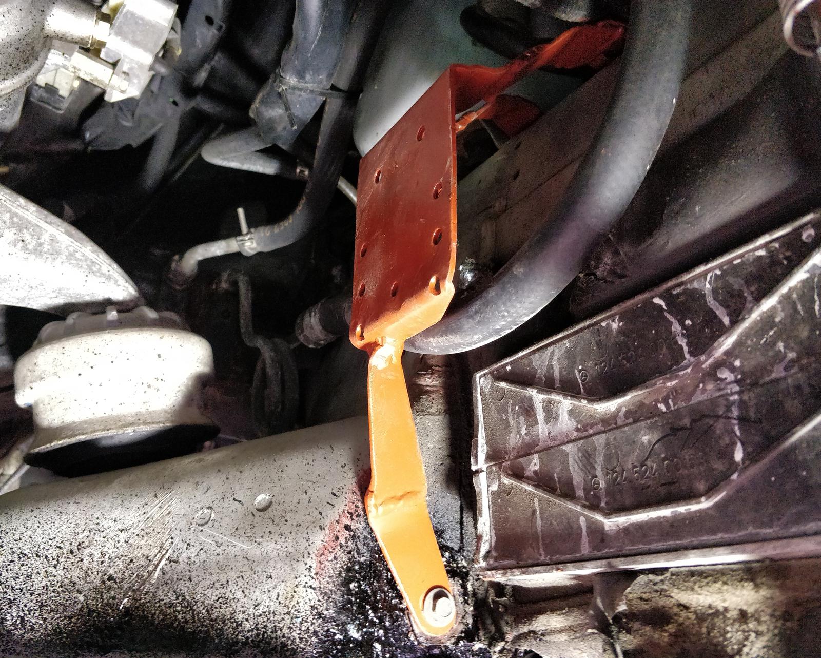
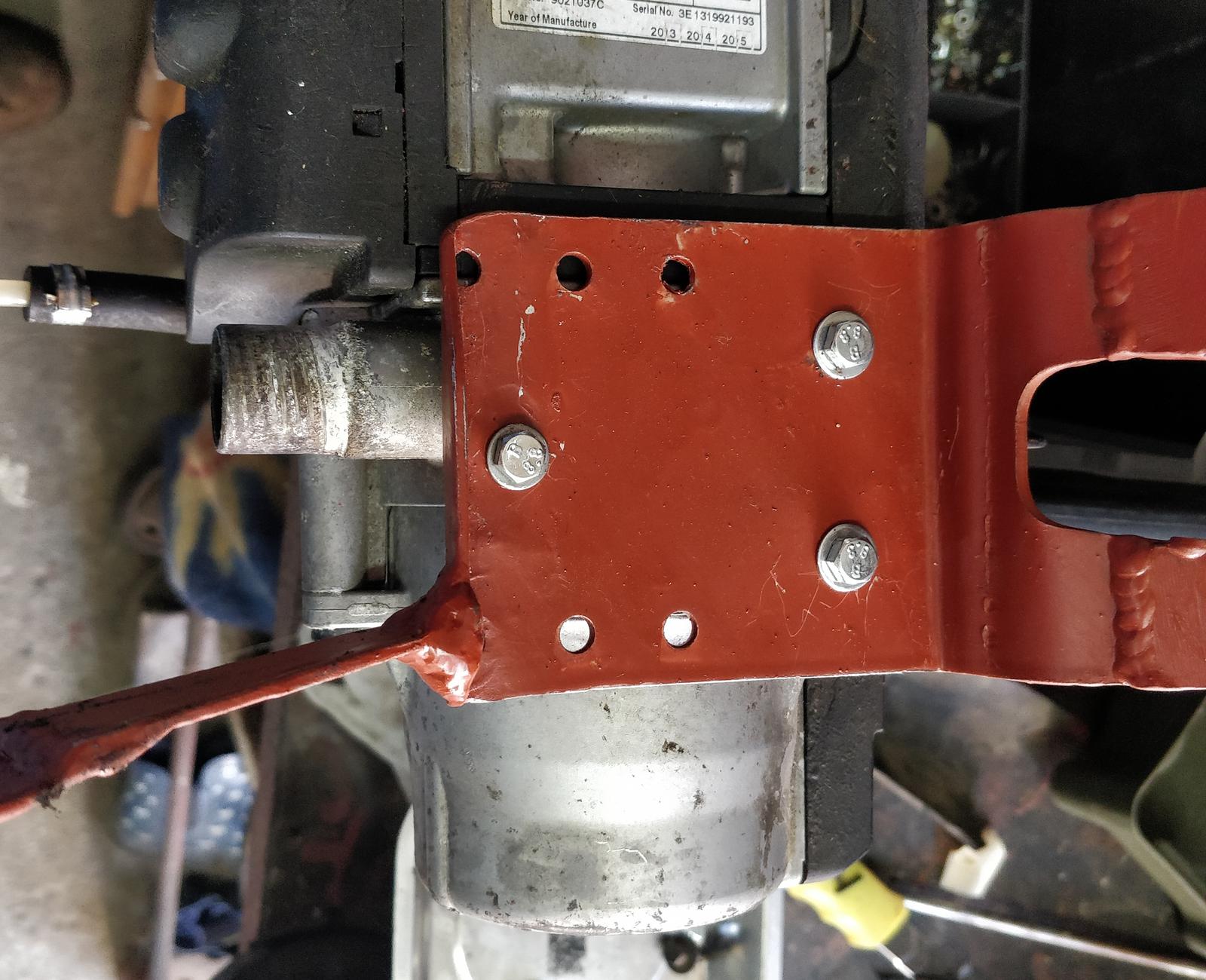
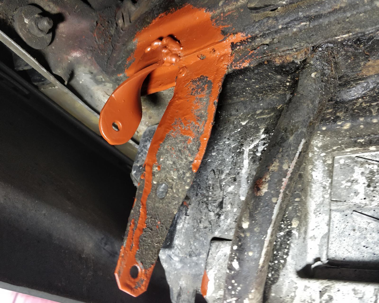
To secure the heater to the chassis, a metal bracket was prepared. One of the upper arms was welded to the original piece of metal that holds the cables (as shown in the first photo). The bracket is fastened to the chassis with three metal screws that were originally in place. I had concerns about whether this would be sturdy enough, but after giving it a firm tug, it appeared to hold up quite well.
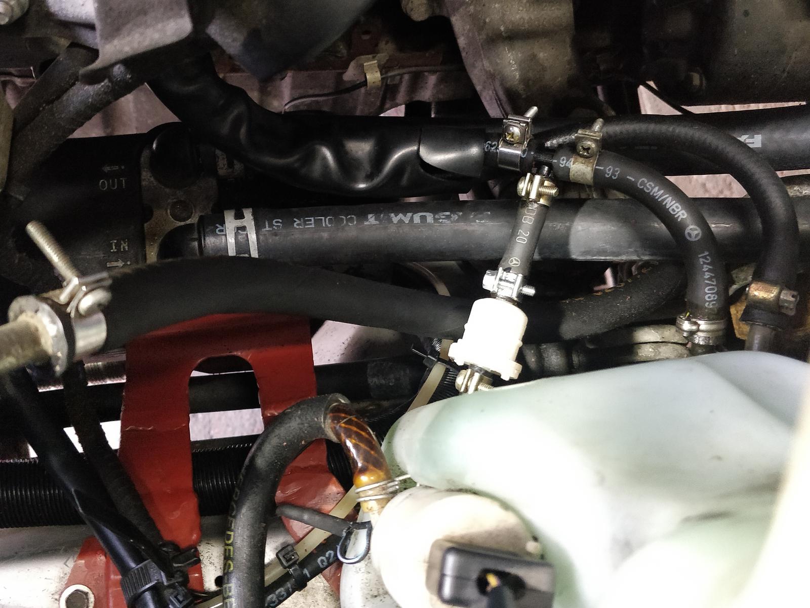
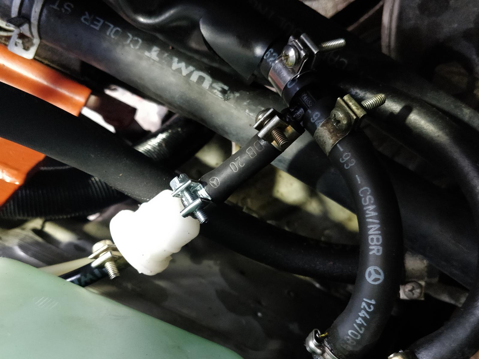
Coolant hoses
On the cooling system diagram, I’ve marked (in red and blue) the preferred locations to insert the heater. The red location is right at the engine’s outlet. The blue location bypasses the windshield washer fluid heater, with the fluid ultimately being heated by the returning coolant, so it doesn’t pose a problem.
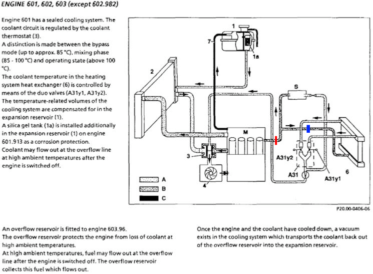
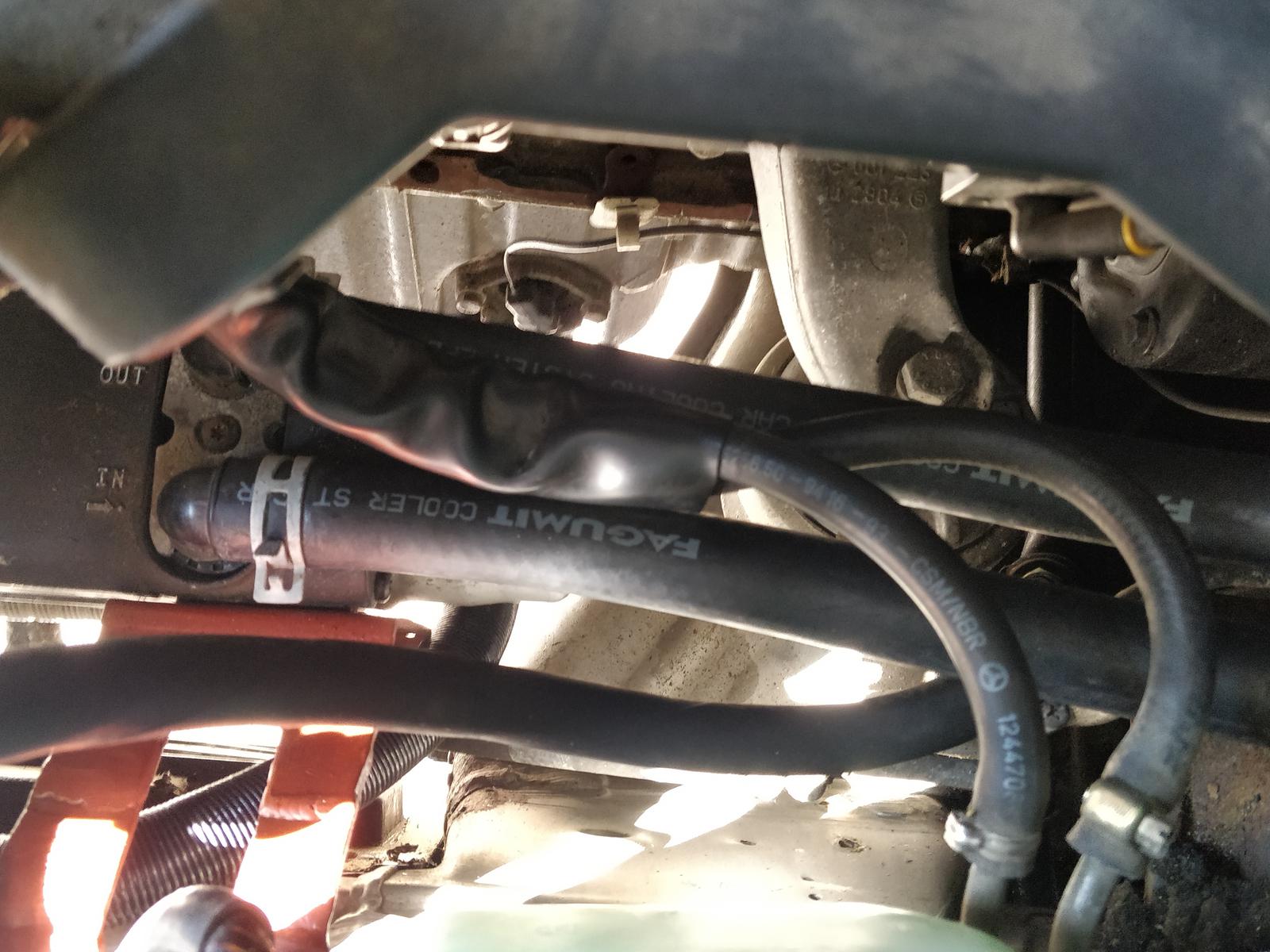
I opted to place the heater at the blue location. This choice was particularly convenient because it allowed me to avoid cutting the original hoses entirely; instead, I redirected and extended them. The hose that originally connected from the engine to the heater core was slightly bent and extended with an 18 mm rubber hose for coolant circuits. The other hose goes directly from the heater to the heater core’s inlet.


Exhaust lines and silencer
Due to space constraints, I had to use a non-original muffler, a smaller one designed for older Webasto models like Thermo Top. The original muffler was too large, which would have disrupted the straight exhaust path. This modification shouldn’t affect the heating process but might result in slightly more noise.
I apologize for not having a photo of the installed silencer. I’ll update this article with photos when I need to perform maintenance in this area, which could happen in the future.


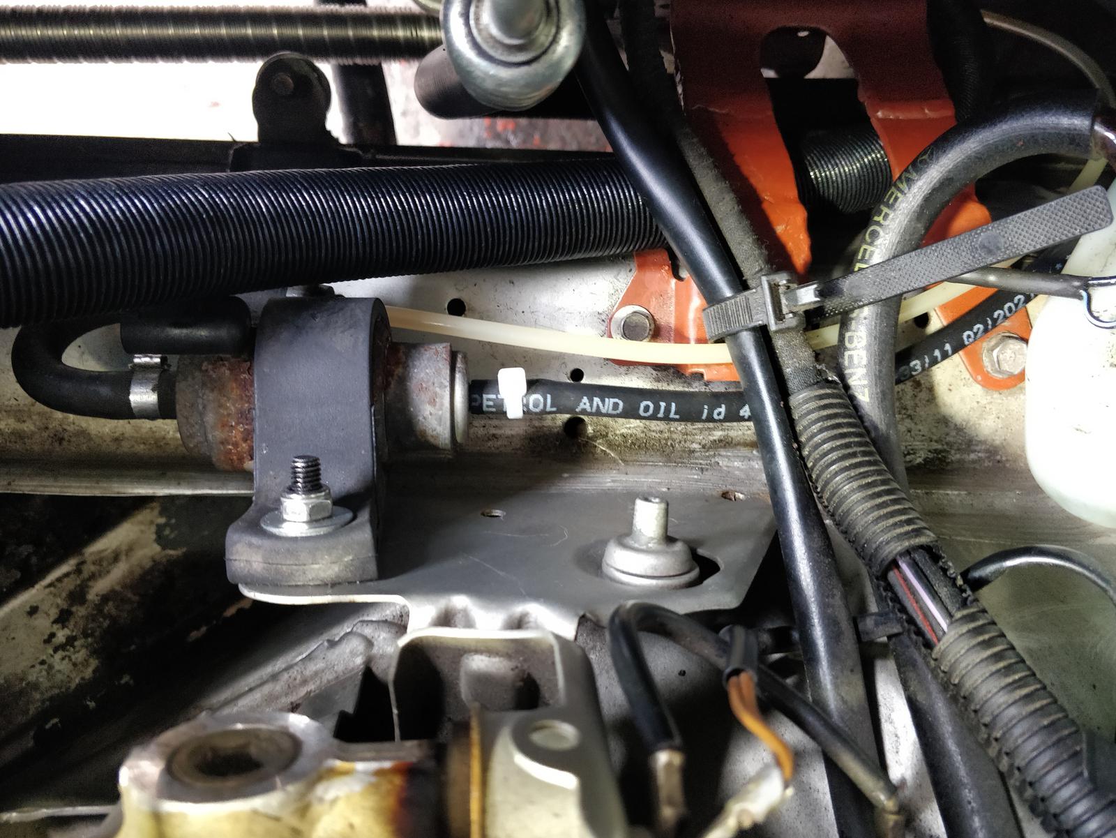
Fuel pump and lines
The manual recommends installing a separate fuel line directly from the tank and placing the pump nearby. However, it’s also possible to utilize the engine’s fuel return lines. The Webasto fuel line has an external diameter of 5 mm, while MB’s fuel line has an 8 mm internal diameter. I used an 8 mm - 5 mm - 8 mm tee-splitter. Additionally, I added a small filter, even though it’s not mentioned in the installation manual, just as an extra precaution.
Warning! When using the engine’s fuel lines, it’s possible to completely drain the tank if the Webasto runs for an extended period! You should never go below the reserve level. A separate line with a standpipe of appropriate length ensures that when the fuel level drops below the lower end, the heater shuts down.
Electrical installation
The W124 is an old car, so its electrical systems lack smartness, meaning there’s no diagnostics and no digital communication. However, this simplicity has its advantages, particularly in terms of modification-friendliness. I’ll provide descriptions for each component separately and then outline the overall wiring.
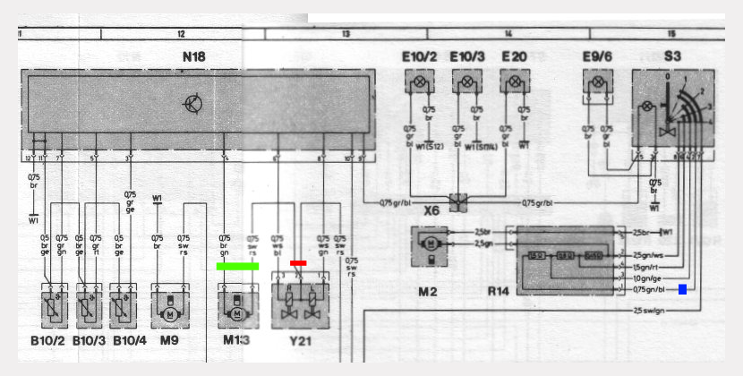
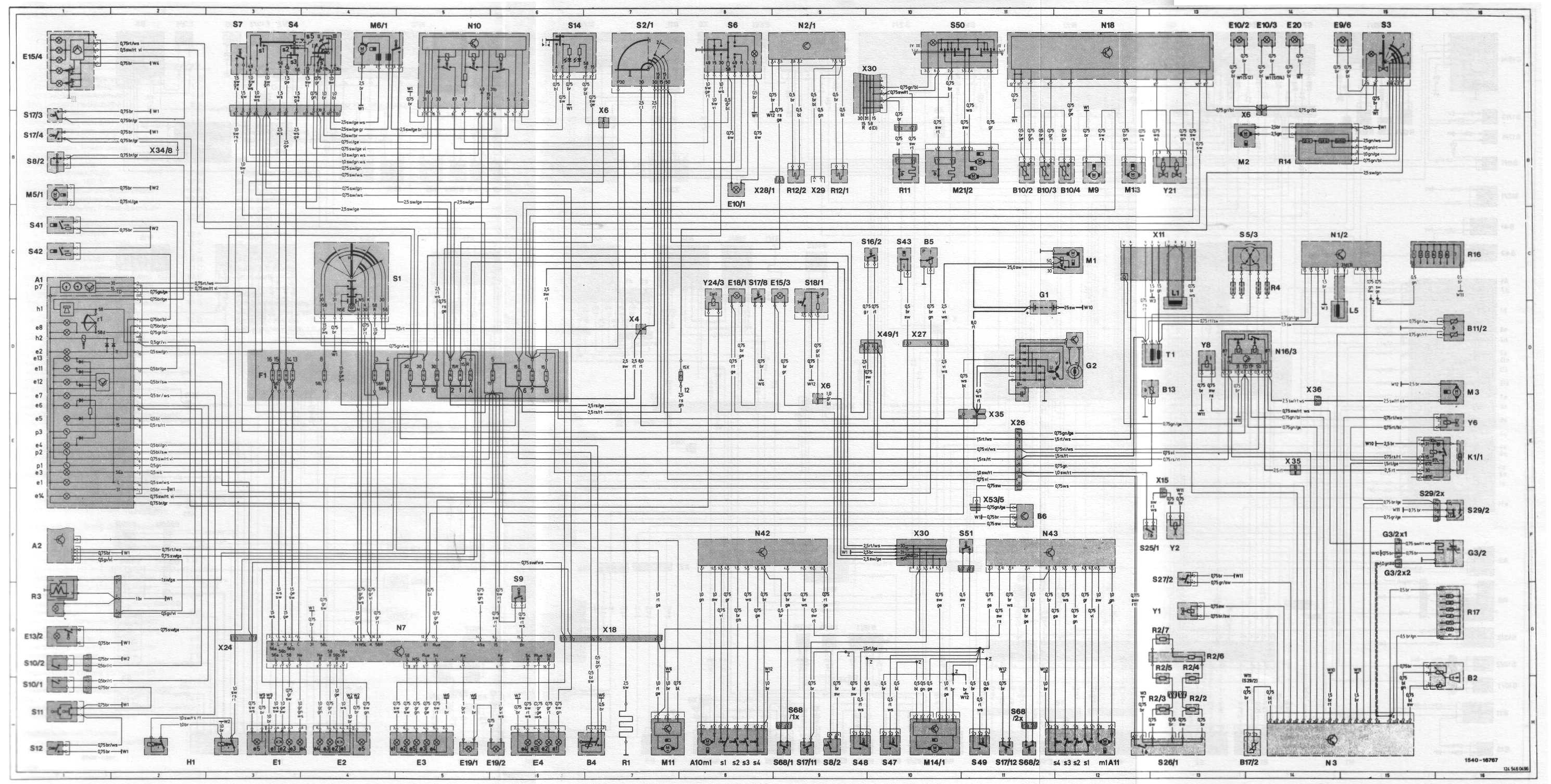
I’ve extracted the relevant portion of MB’s electrical schematic and color-marked the important locations:
| Schematic marking: | Function: | Cable marking: |
|---|---|---|
| green | circulation pump M13 |
brown/green + black/pink |
| red | +12 V of valve solenoid Y21 |
black/pink |
| blue | first gear of the blower | green/blue |
Circulation pump and valves
The official manual assumes that a separate brushless circulation pump should be installed. However, I opted to use the one that’s already a part of the
interior heating system. This choice means that we need to drive the pump both from the Webasto and the car’s native heating system. Let’s look again at
the coolant circuit. Hot coolant from the engine (or Webasto) flows to the heater core and then to the electromagnetic valves A31y1 and
A31y2. These valves are controlled by the car’s heating electronics and are normally open. We need to ensure they aren’t powered when the
Webasto is running. Referring to the electrical schematic, we see that the valves are driven open-collector, so disconnecting the +12 V supply ensures they
remain fully open.
The circuit needs to accomplish the following:
- Disconnect the solenoids of the valves from +12 V.
- Disconnect the circulation pump from the car’s installation and connect it to the Thermo Top Evo.
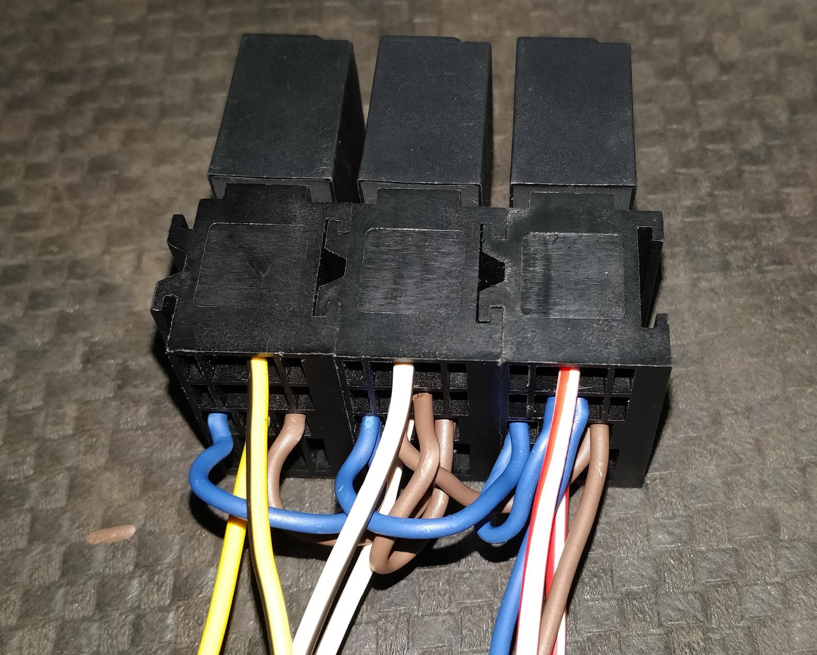
This was achieved using three automotive relays, as shown in the schematic. You can refer to this automotive SPDT relay guide for guidance on wiring a standard car relay.

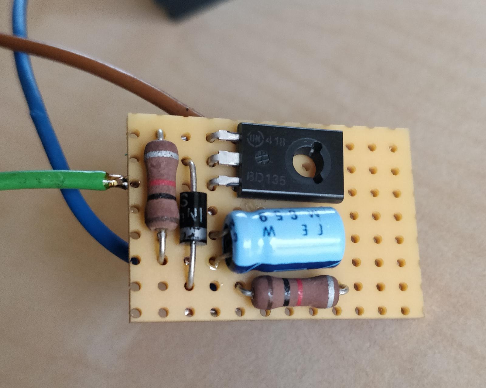
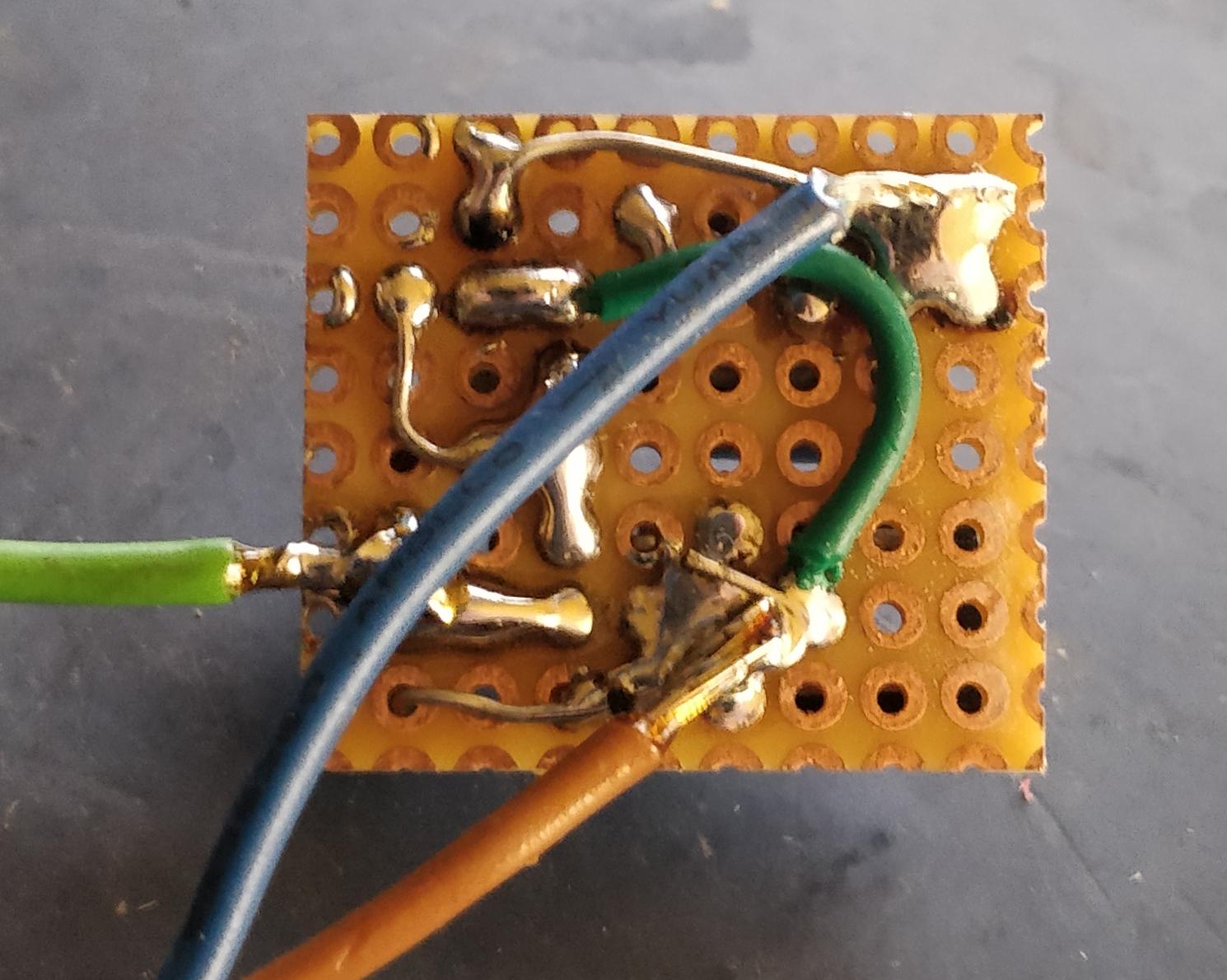
But why the transistor with accompanying elements? It’s because Webasto constantly checks if the pump is connected by sending 2 ms pulses of 12 V every 100 ms when heating is turned off. Without the delay circuit, this would result in audible clicks in the relays, which can be annoying and power-consuming. The transistor, along with the capacitor, tricks the Webasto into recognizing this circuit as a brushless motor.

Blower
The blower is originally controlled by the mechanical switch S4 and resistor array R14. The switch simply connects subsequent
resistors in parallel for each gear. I’ve marked the cable for the first gear with a blue rectangle on the schematic. I used a genuine MB
STST relay with an integrated fuse. I replaced the fuse with a 25 A one, which matches the blower’s main fuse rating.
The relay simply connects the 12 V supply to the first gear resistor. However, due to the way switch S4 operates, when the second gear is
selected, the blower will run on the second gear, and so on. This could lead to a rapid drain of the car battery. Ideally, an SPDT relay should have been
used, but I didn’t have one compatible with the fusebox sockets. It’s important to ensure that the switch is never left on the maximum gear setting when
the Webasto is scheduled to run.

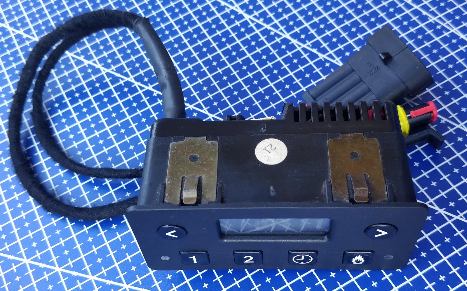
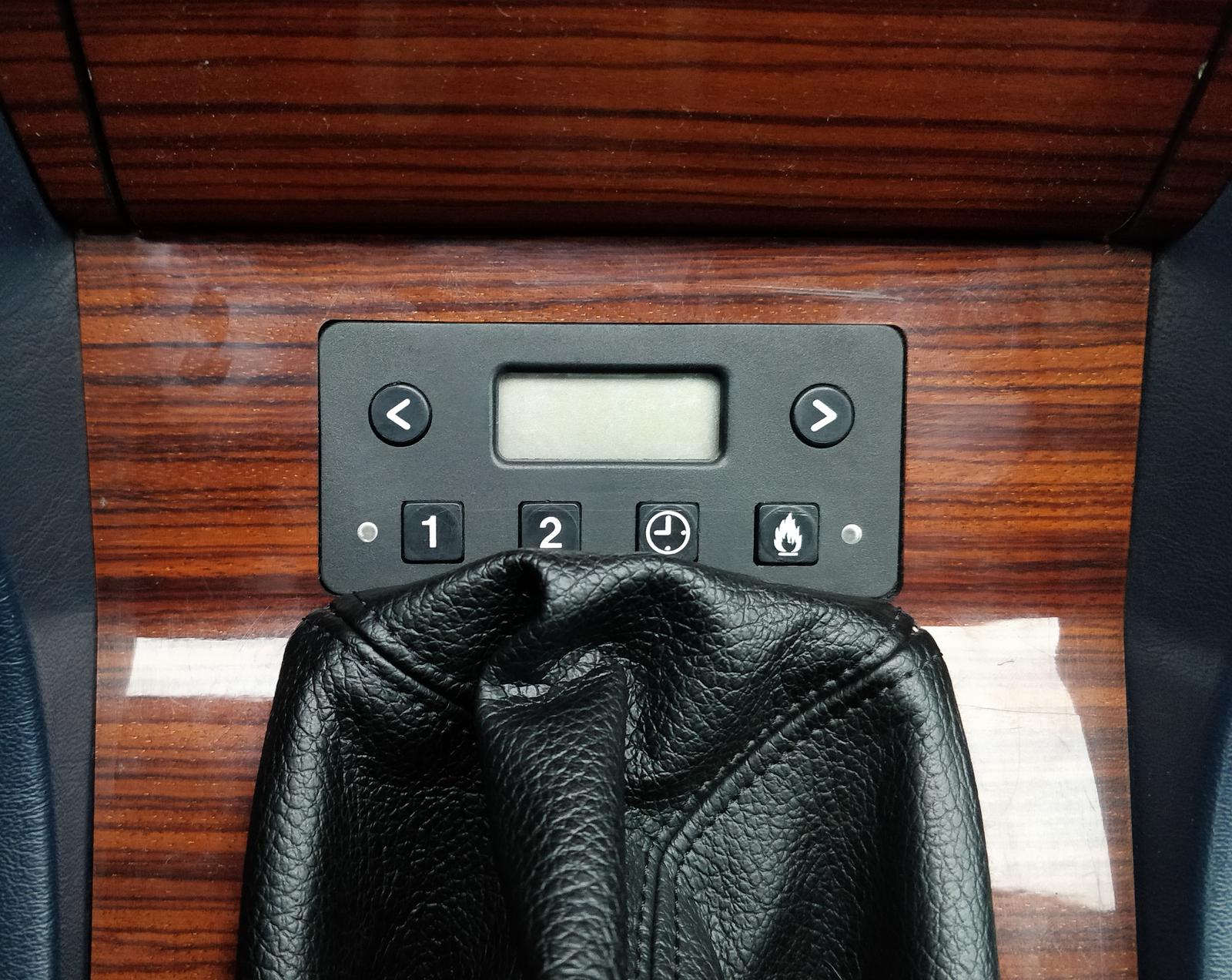
Timer
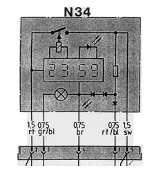
My timer was extracted from another W124, which had Webasto as an option. This timer, known as 1522, was used in various vehicle models, albeit with slight variations. It’s available in versions for both 12 V and 24 V systems. The timer I obtained was manufactured specifically for Mercedes-Benz, as indicated by the MB-specific connector.
Below is a block schematic of the timer extracted from Mercedes-Benz documents. Originally, the pinout was as follows:
| Color: | Function: |
|---|---|
| red | +12 V supply voltage, always present. |
| brown | Ground. |
| gray/blue | +12 V illumination light, lights up the buttons. |
| black | Supply voltage for the heater, switched on by an internal relay, originally connected to the BBW/DBW46 controller box. |
| red/blue | A bit tricky, unused in some installations. When not connected, green status LED lights up when relay is on. Looking at the schematic of BBW/DBW46 we can determine that the LED is shorted by circulation pump. So the diode lights up only when circulation pump is running. |
I thought it would be a good idea to replace the green status LED with a red-green one. The green one will still be powered from the relay, while the red one will be powered from the circulation pump. In this case, we can visualize the following states:
| Color: | State: |
|---|---|
| green | Timer activated Webasto, but it haven’t started running yet. |
| yellow | Webasto is activated and circulation pump is running. |
| red | Webasto was turned off, but the pump is still running, indicating the system is in cooldown. |
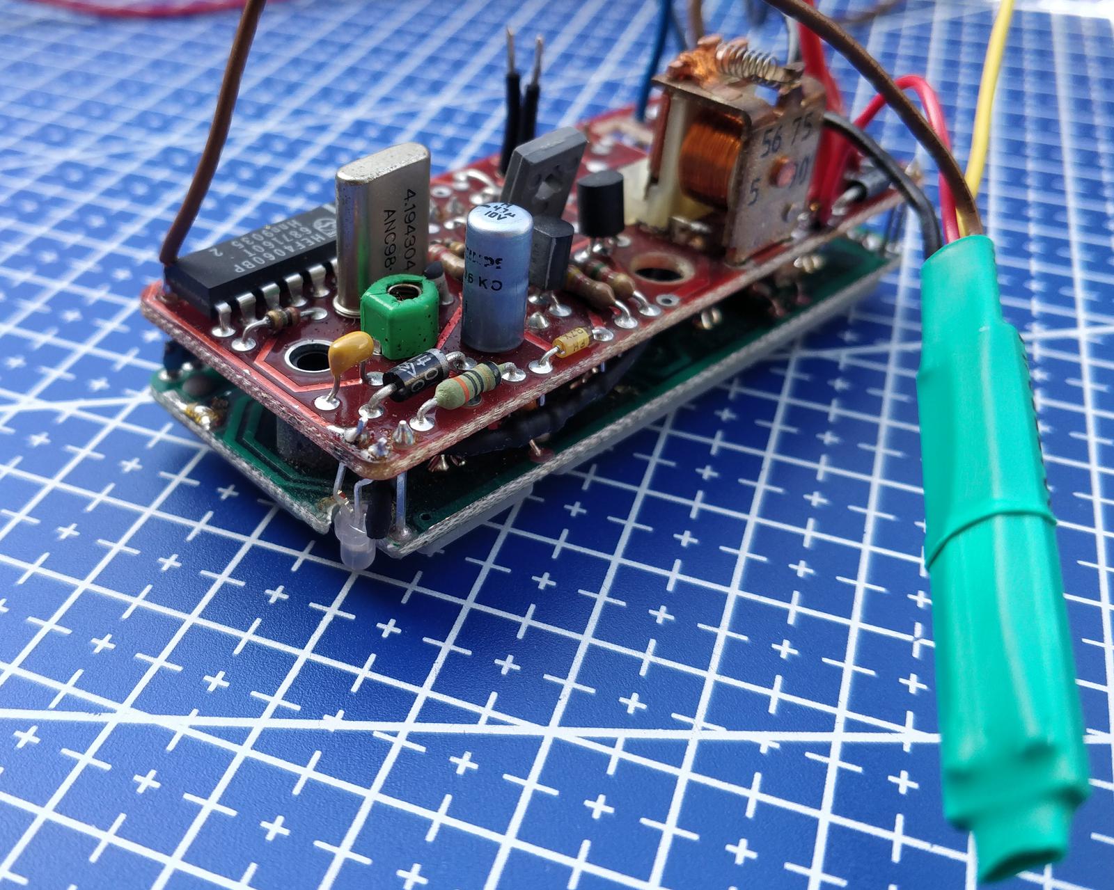
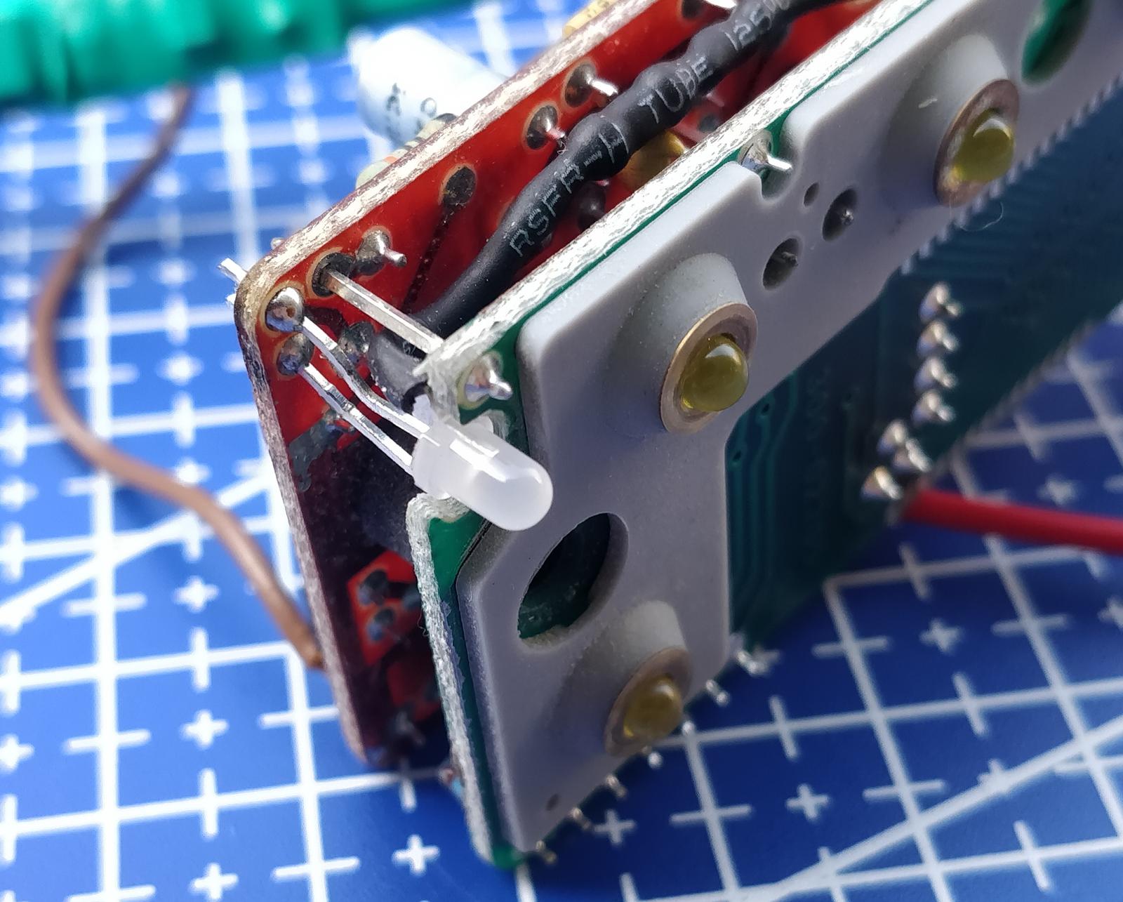
The old green diode was removed, and a fragment of the board was cut. The green part of the new diode was soldered to the old pads, while the red part was connected to the circulation pump through a 680 Ω resistor.
Another issue that required attention was that the Thermo Top Evo only accepts commands sent through W-BUS. The analog timer is essentially just a switch. Fortunately, I found a small module named OLB 400, manufactured in Poland and sold by this seller. The module generates start and stop commands just like the 1533 digital timer.
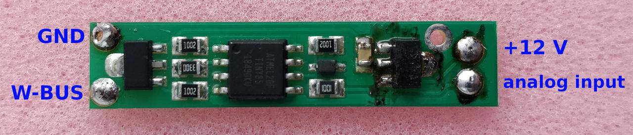
However, I noticed that the module drew a significant idle current, almost 17 mA, which was unacceptable. I contacted the manufacturer, and they sent me a new module with updated firmware. The idle current dropped to ~6 mA, which was better but not ideal. This was caused by the on-board 78L05 stabilizer, which normally draws about ~5 mA of bias current. To address this, I removed the stabilizer and powered the module directly from +5 V, which is available on the timer board (at pin 16 of the ‘4060 IC, to be exact). This reduced the overall current consumption to ~2 mA when idle, which is completely acceptable.
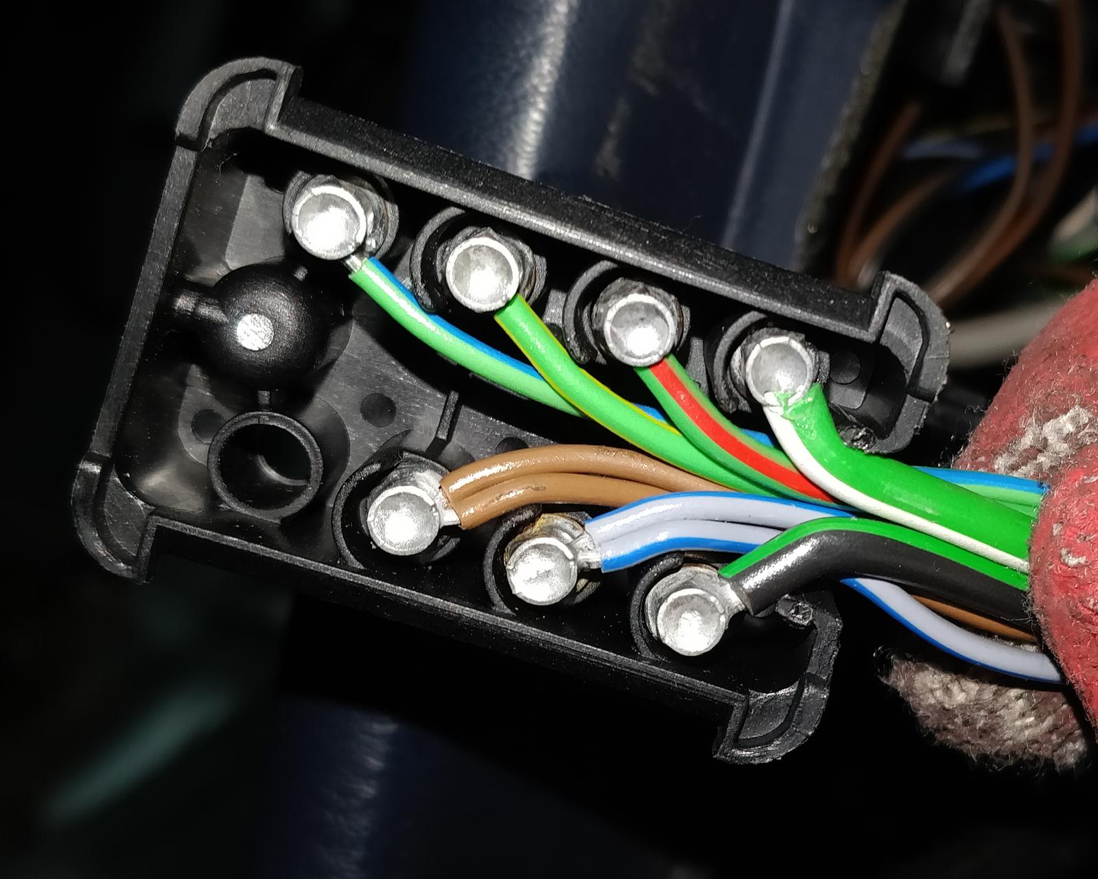
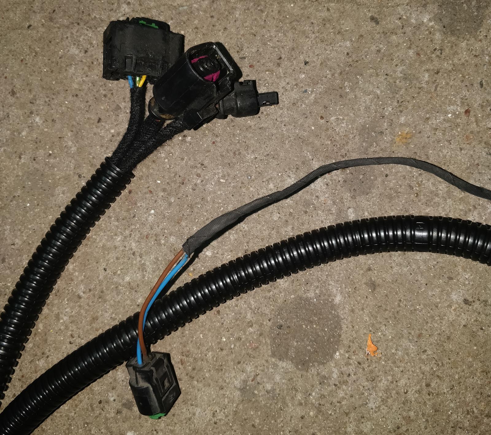
I made a new wiring harness for the timer with two Superseal connectors: a 4-pin and a 2-pin. This provided a total of 6 pins, but only 5 are used:
4-pole plug:
| Pin number: | Function: |
|---|---|
| 1 | Supply +12 V, always available. |
| 2 | Ground. |
| 3 | Circulation pump - running indicator. |
| 4 | +12 V console illumination. |
2-pole plug:
| Pin number: | Function: |
|---|---|
| 1 | W-BUS |
| 2 | +12 V for independently starting the heater, perhaps by remote control. Currently unused. |
Wiring everything together
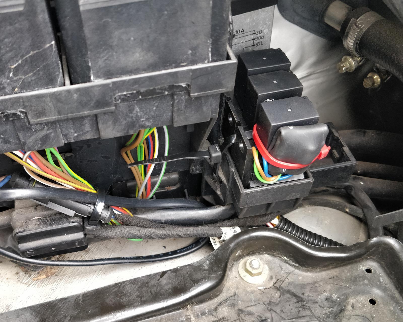
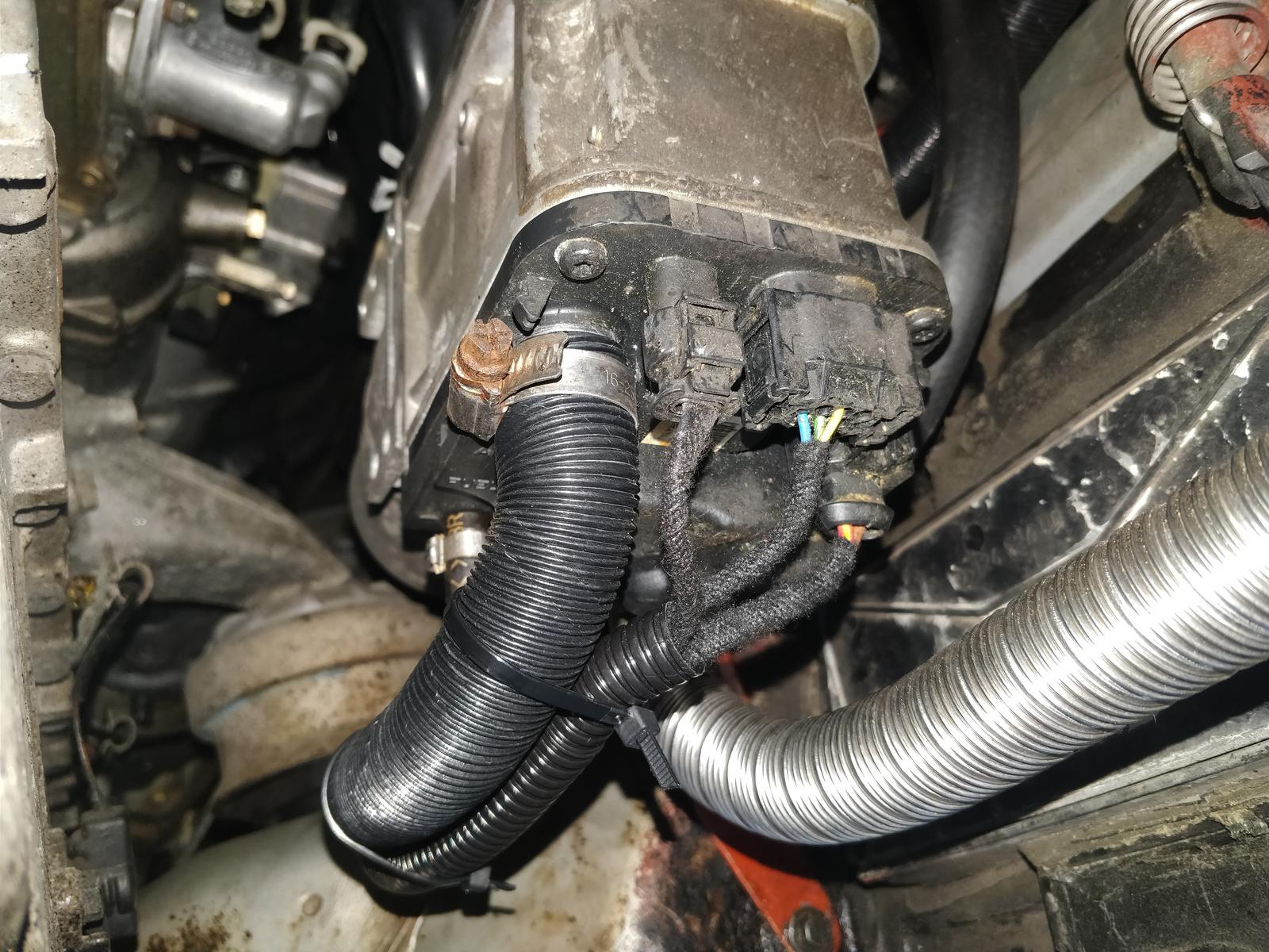
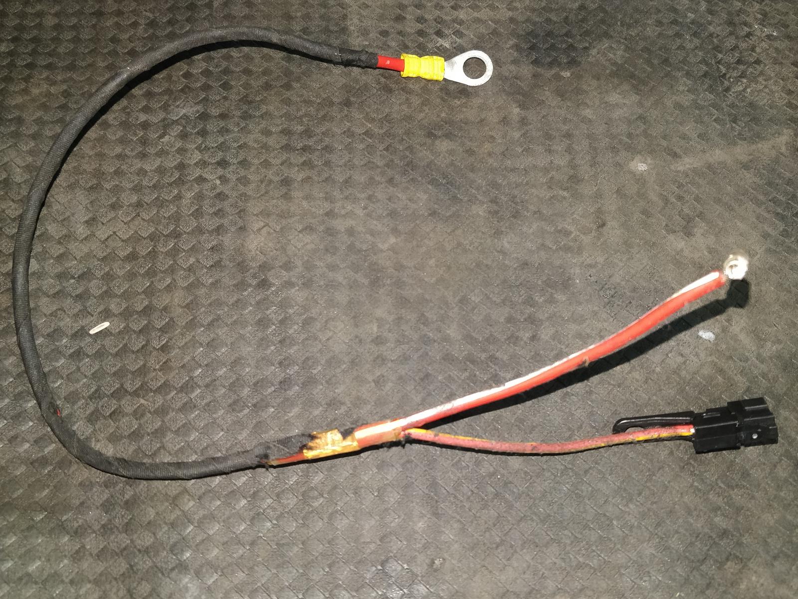
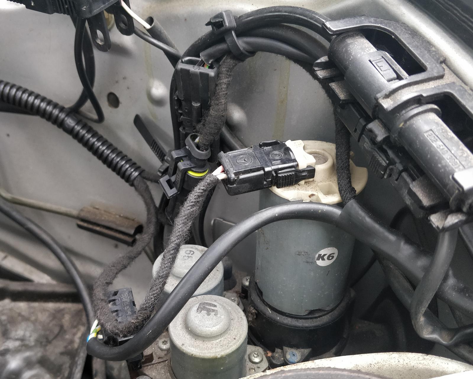
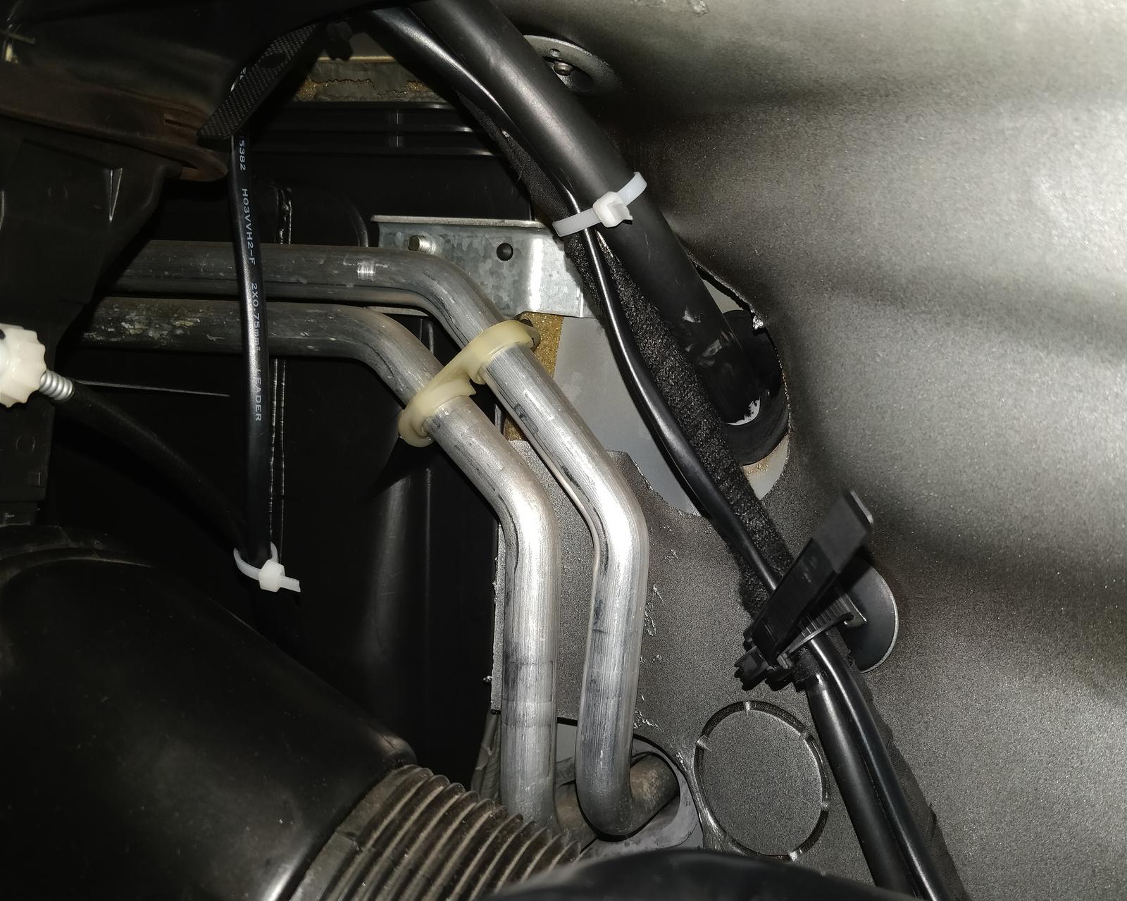
I crafted a wiring harness, enclosing the cables within wire conduits and covering their respective ends with wiring harness tape. This harness originates at the heater itself, branches off at the fuel pump, and terminates inside the fusebox.
Inside the fusebox, you’ll find fuse E for the heater itself and the blower relay with its integrated fuse. The +12 V supply comes from the binding post located just below the box; ground connection is also available there. I added three fuses in total:
| Fuse: | Value: | Description: |
|---|---|---|
| Main | 20 A | Placed inside the fusebox in socket numbered E. Originally reserved for heated seats, which I don’t have. |
| Blower | 25 A | A dedicated fuse for the blower when activated by the Webasto, matching the value of the original blower fuse. |
| Timer | 1 A | A dedicated fuse for the timer, mounted on the cable. |
The cables from the fusebox were routed within the existing cable tray beneath the steering wheel and then extended to the center console. From there, they diverge to the blower, the timer and the circulation pump driver. The blower cable should have a cross-section of 2.5 mm2 to accommodate potentially high current loads, while the cross-section of the other wires is not critical.
The timer is connected using Superseal connectors. The harness then follows one of the existing cables to the right side of the vehicle and passes through one of the cable glands into the compartment behind the battery. Here, it connects to the circulation pump relays.

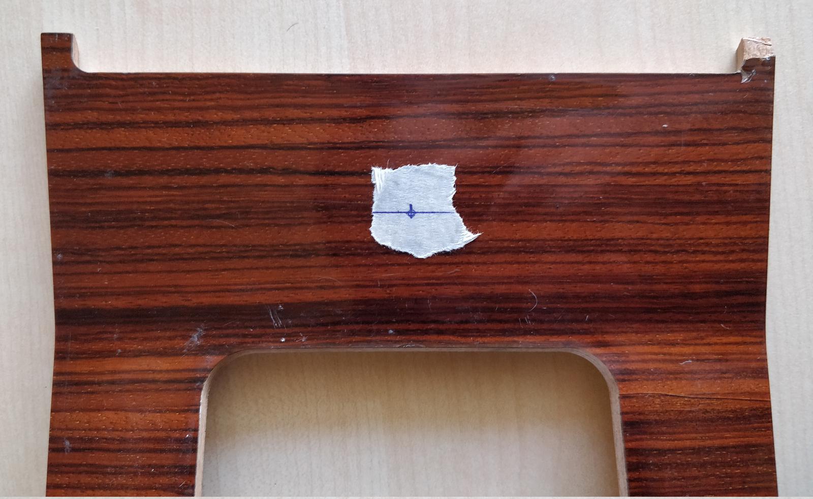
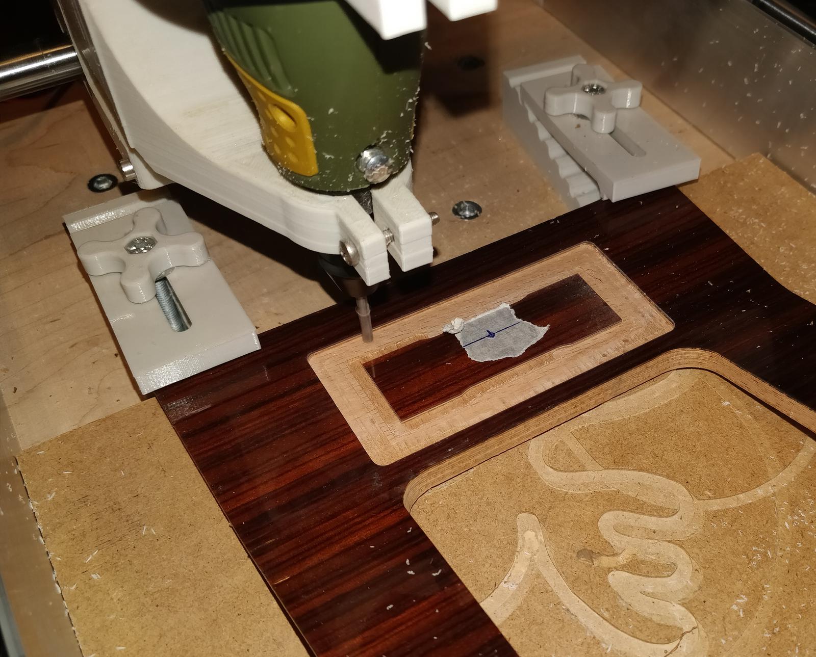
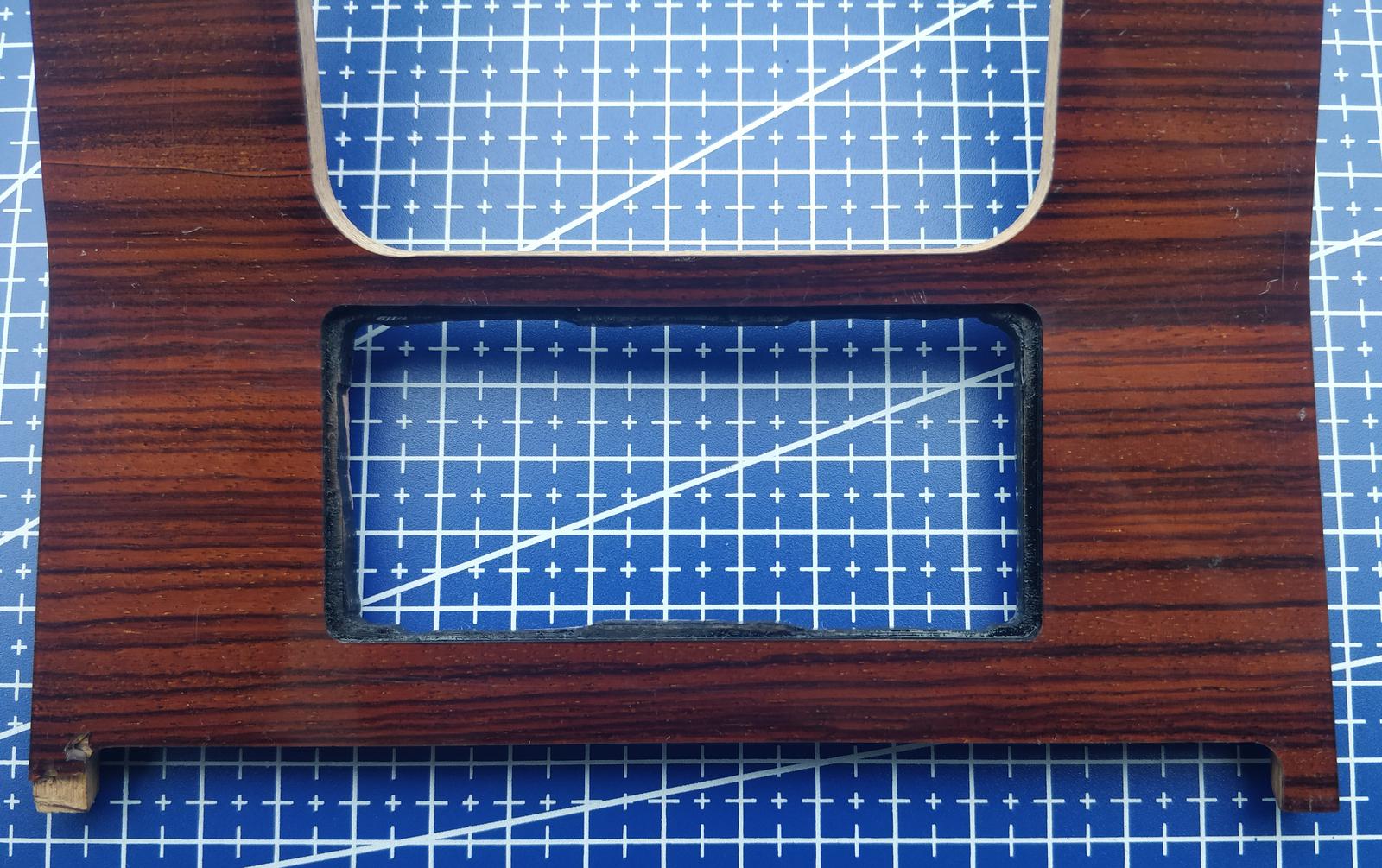
Milling hole for the timer
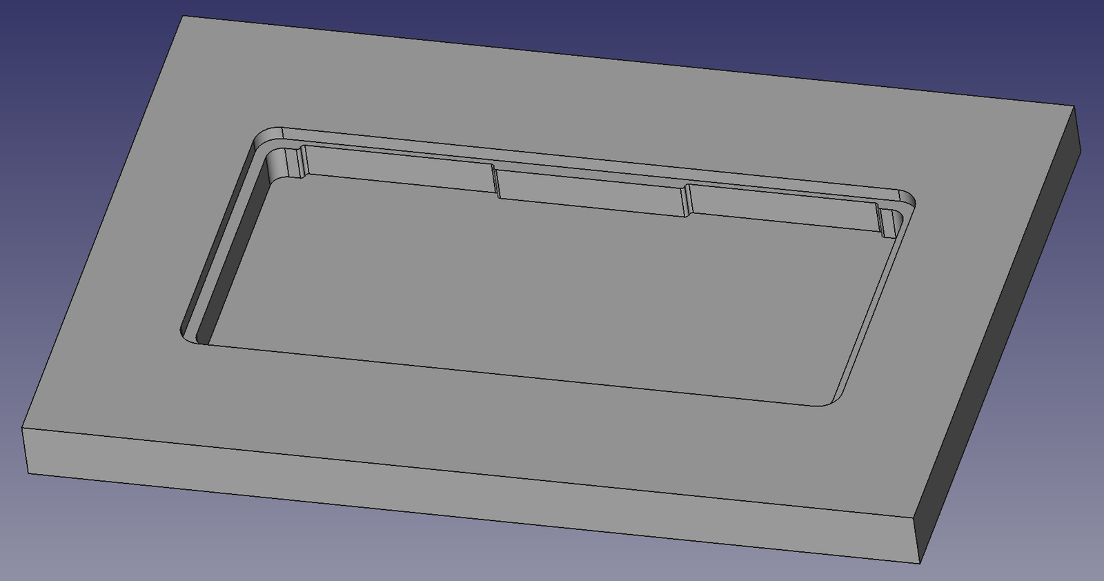
The center console of the W124 is constructed from veneered plywood with a lacquer finish. Cutting a hole in it by hand would be nearly impossible, so I opted to use a milling machine. I designed the hole’s shape using FreeCAD. Design files are available in the project repository. The repository contains the FreeCAD project as well as the Grbl file. Warning! I cannot guarantee that the Grbl file is 100% correct, as I encountered some issues with the milling machine going haywire, so use caution!
I borrowed a DremelCNC, a small CNC milling machine constructed from 3D-printed parts, as described in this guide. It is Grbl-compatible; I myself controlled it using CNCjs, although several other tools are available. The spindle was powered by a Proxxon FBS 240/E mini drill.
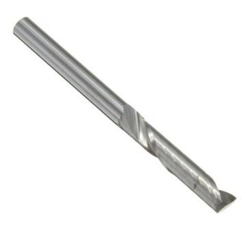
With a Drillpro 3.175 mm end mill (SKU192030, as shown in the photo), it performed admirably. The milling parameters were as follows:
- Layer step down: 0.2 mm. This value is relatively low to ensure that the lacquer is removed without chipping.
- Horizontal feed: 5 mm/s.
- Vertical feed: 2 mm/s.
- Spindle speed: ~15,000 RPM, which drops to ~10,000 RPM under load. This corresponds to setting 15 on Proxxon’s dial.
The starting point is in the middle of the hole, as seen in the photos. It should be positioned 11 mm + 21 mm = 32 mm from the upper edge (by upper, I mean the side toward the front of the vehicle). These measurements were taken from another car that had Webasto as an option. In hindsight, I should have moved the reference point about ~5 mm upward to make the timer more visible; currently, the buttons are somewhat obscured by the gearshift from the driver’s perspective.
The CNC encountered issues when finishing, but fortunately, the visible area had already been successfully milled. I had to cut the remaining hole with a jigsaw.
Final thoughts
I managed to complete the installation just before the winter began. After several test runs in outdoor temperatures ranging from 0°C to -8°C , I wholeheartedly recommend installing this system. Snow effortlessly slides off the pre-warmed vehicle, and the comfort of stepping into a cozy, pre-heated interior is truly invaluable. If you have any questions about the installation, please feel free to ask, and I’ll be happy to provide answers.