Determining the pinout of the unknown vacuum fluorescent display

Vacuum fluorescent displays are cool. Although not as iconic as Nixie tubes, they do nicely as retro displays. Since they are custom-made for a specific device, their datasheet is not available publicly. The good news is that they are quite easy to reverse-engineer.
Where to find them
If you’re looking for vacuum fluorescent displays, you might find them in:
- VCRs or videotape recorders: custom-made, small digits, often with multicolored segments
- Microwave ovens and other kitchen appliances: simple 4-digit displays suitable for real-time clocks
- Old desktop calculators: numeric digits with decimal separators. Often displays more than six digits and can display time with 1-second resolution
- Cashier equipment: bright, dot-matrix displays capable of displaying text
Aside from the display, it’s a good idea to salvage the power transformer because it often has a dedicated windings for anode voltage and the filament.
How do they work
The principle of operation for vacuum fluorescent displays is described in detail on Wikipedia, there’s no need to repeat it here. A single segment has three electrodes:
- Filament, heater, or cathode - several tungsten wires spanned along the length of the display.
- Anode - the glowing segment covered with phosphor.
- Grid - a fine wire mesh between the anodes and the filament. Each digit has a separate grid, which enables multiplexing.
To light the segment up, you have to supply voltage in the range of 30–50 V to both the anode and the grid. Shorting the grid to the cathode shuts the whole digit down. This is how multiplexing is done. VFDs have an advantage over nixie tubes in that they don’t require a separate driver for each segment. So this is basically a direct-heated triode. Some folks have even made audio amplifiers using them!
A vacuum fluorescent display filament should be powered by alternating current from a center-tapped transformer with the center tap connected to the ground. If you provide both anode and filament voltages from the same power supply, the voltage drop along the length of the filament will cause the effective anode-cathode voltage to change for every digit. Let’s say your anode voltage is 30 V and filament voltage is 5 V, with the ground connected to the left pin. In this case, the leftmost digit has an anode-cathode voltage of 30 V, but the rightmost has only 25 V. This will contribute significantly to brightness changes.
Usually, devices containing vacuum fluorescent displays have accompanying power transformers, so you may salvage both parts at once.
Examination
For the purpose of this article, I have examined two vacuum fluorescent displays:
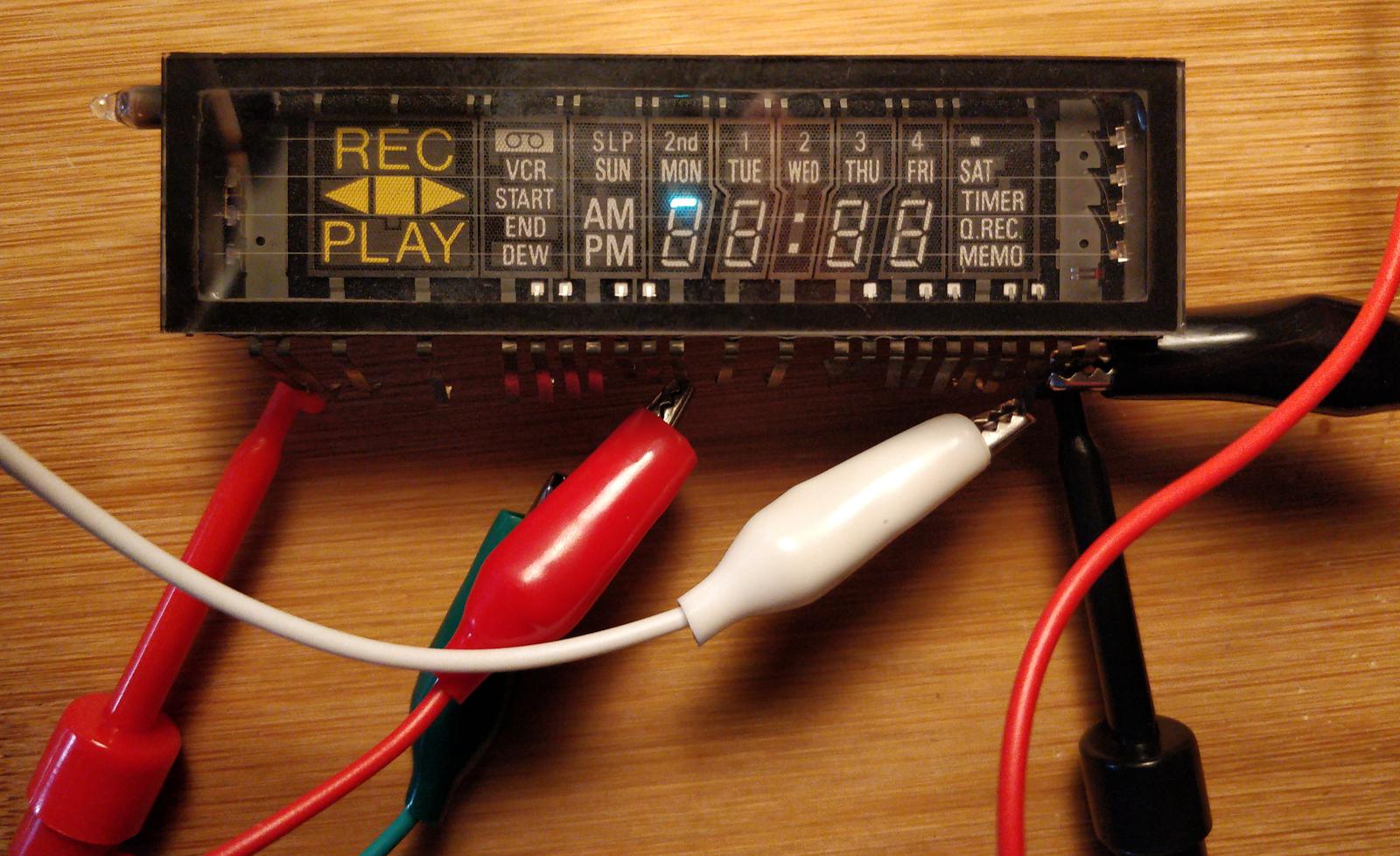
- Futaba
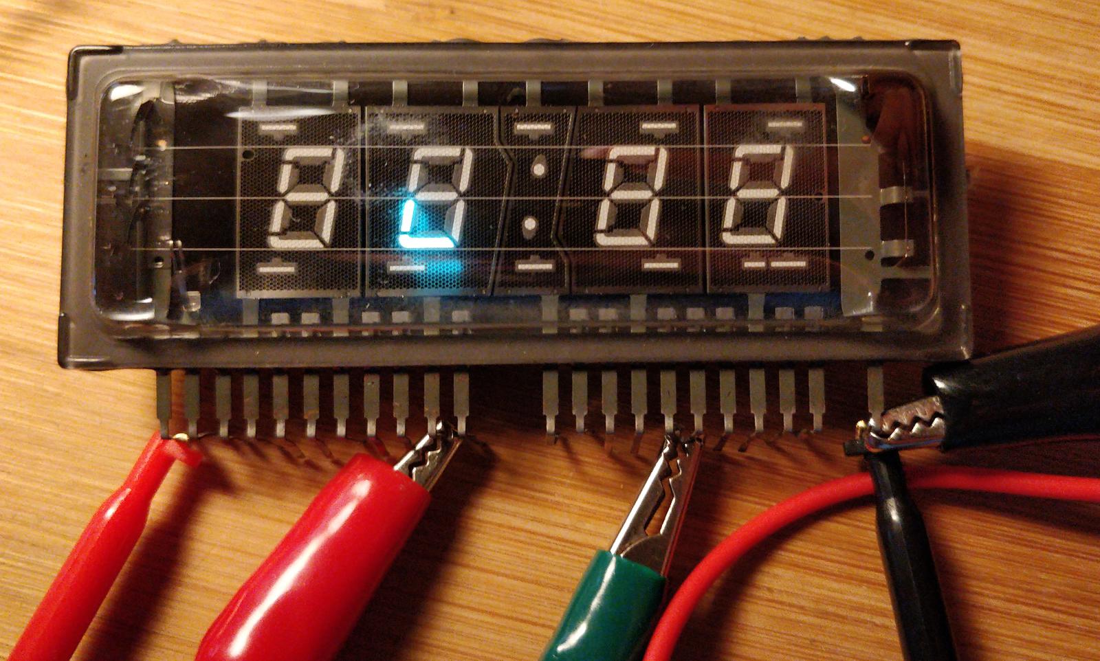
9-BT-22ZK- 23 pins, salvaged from an old videotape recorder. - NEC
FIP4B9F- 22 pins, salvaged from microwave oven.


The first thing to do is to check whether the display is airtight. When you look at the corner of the VFD, you’re supposed to notice a dark and shiny getter spot. If the getter is white, the vacuum within the display is lost, and the VFD is irreversibly broken.
Determining the filament voltage
The majority of them have easily determinable filament pins just by looking through the glass. Double-check this using the ohmmeter. The cold filament is supposed to have a resistance of several ohms. My displays:
- Futaba 7.5 Ω
- NEC 8 Ω
It’s widely assumed that the safe voltage for powering the filament is when the filament just barely starts to glow dark red. For testing, you should use a variable voltage power supply. Connect it to the filament and observe it in a dark room. You should gradually increase the voltage by 0.1 V starting from 2 V. Wait a couple of seconds after each increase. Majority of VFD filaments start to glow at voltage between 3–5 V. My displays:
- Futaba 2.9 V
- NEC 2.7 V
I assumed that both of them can be safely powered from 3 V power supply.
Identifying anodes and grids
You’ll need:
- Power supply for the filament - 3–5 V AC or DC, as determined in the previous step.
- Power supply which gives 24–50 V DC, not necessarily variable. I used 30 V lab power supply.
- Some crocodile clip cables.
- Some resistors in range 33–100 kΩ, I used 51 kΩ.

Follow these steps:
- Power up the filament.
- Connect the negative terminal of the 30 V power supply to one of the filament pins.
- Connect at least two crocodile clips to 30 V through 51 kΩ resistors.
- Connect one of the clips to the first grid you can identify by looking through the glass.
- Swipe the other crocodile on the remaining pins. Some of the segments under the selected grid should glow, which marks the pin as an anode.
- Proceed with the remaining grids.
This way, you can easily determine the pinout of almost any VFD.
Determined pinout
For demonstration purposes, I reverse-engineered the pinouts of the two aforementioned VFDs. Pins and digits are numbered from left to right. I skipped determining the output of the additional segments and limited myself to just digits.
Futaba 9-BT-22ZK
Filament voltage ~3 V, 100 mA.
| Pin number | Function |
|---|---|
| 1, 2 | filament |
| 6 | colon’s upper dot anode |
| 7 | colon’s lower dot anode |
| 9 | anode segment G |
| 10 | anode segment F |
| 11 | 1st digit grid |
| 12 | 2nd digit grid |
| 13 | colon’s grid |
| 14 | 3rd digit grid |
| 15 | anode segment E |
| 16 | 4rd digit grid |
| 17 | anode segment D |
| 18 | anode segment C |
| 20 | anode segment B |
| 21 | anode segment A |
| 22, 23 | filament |
NEC FIP4B9F
Filament: ~3 V, 100 mA.
| Pin number | Function |
|---|---|
| 1, 2 | filament |
| 4, 7 | 1st digit grid |
| 10 | 2nd digit grid |
| 12 | colon’s grid |
| 13 | anode segment G |
| 14 | anode segment F |
| 15 | 3rd digit grid |
| 16 | anode segment E |
| 17 | anode segment D |
| 18 | anode segment C |
| 19 | 4th digit grid |
| 20 | anode segment B |
| 21 | anode segment A |
| 22 | filament |