Automatic USB mains switch for a USB-controlled power strip

Warning
Working with high voltage can be lethal—disconnect power before starting and verify all wiring is correct and properly isolated before powering up.
I wanted to buy a USB-controlled power strip that shuts down devices when my PC goes to sleep. Life is not that easy, though: all available USB power strips are quite dumb—they directly use the +5 V from the USB port to drive the relay, and that’s it. The problem is that most motherboards don’t disable USB supply voltage in sleep mode; the PC has to be turned off completely for that to happen.
I realized I had to build a custom switch that detects USB bus inactivity. This great tutorial about the USB physical layer specifies that the USB host (namely, a PC) generates a start-of-frame packet every millisecond; otherwise, the device should enter suspend mode. Communication ceases when the computer is suspended. This is ideal for my use case.
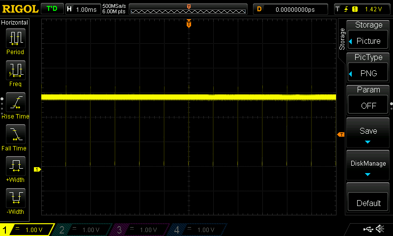
Let’s look at the screenshot below visualizing the signal on the USB D- line. Indeed, every millisecond, there’s a short negative pulse.
The idea is to make an extremely simple USB device with no communication capabilities (no endpoints defined) that just listens to bus activity and shuts
the relay down after some time of inactivity.
Hardware - relay module
In fact, there’s no need to develop one, because there already exists a popular Chinese USB relay module, sold on AliExpress and eBay
under various names and colors. I used the very same one in my eavesdropping USB communication tutorial. It identifies itself in the USB descriptor as
vendor: www.dcttech.com, product: USBRelay2.
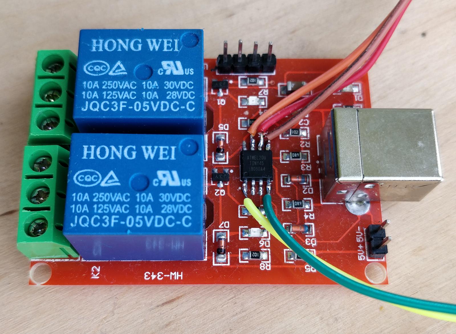
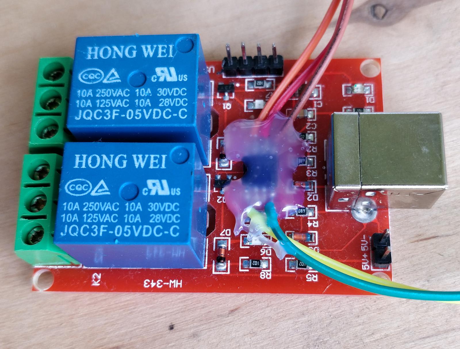
On the PCB, there are a few components, most importantly ATtiny45. To upload new firmware through ISP, I soldered wires and secured them with hot glue. Then, I performed a successful communication test with the microcontroller using avrdude:
avrdude -c usbasp -p t45
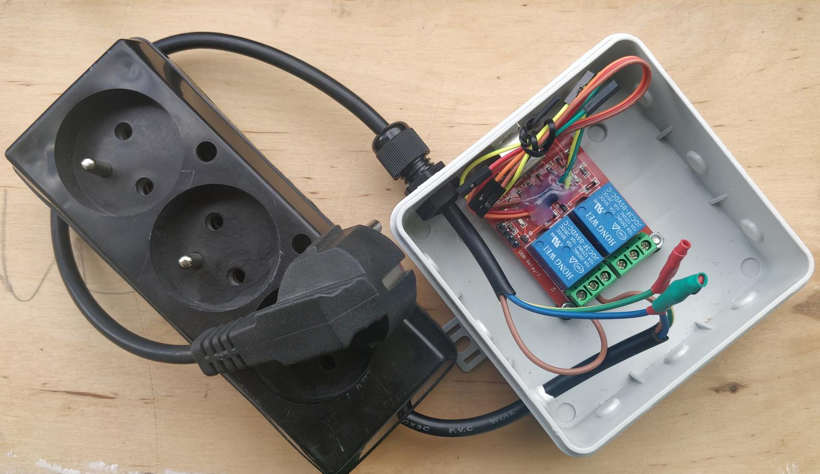
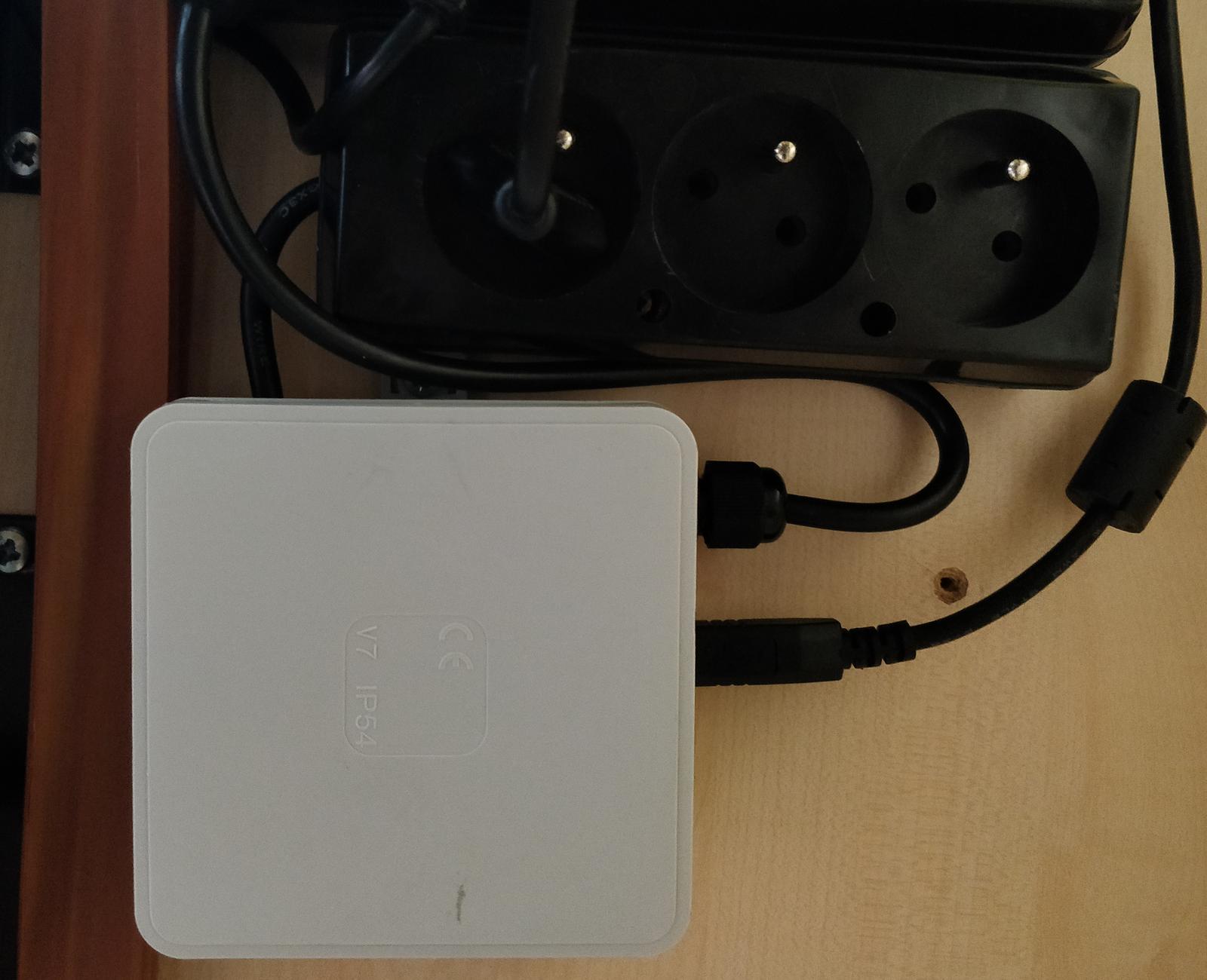
After I was done writing custom firmware, I added power cables and the power strip. I should have also added a fuse, for good measure. The whole contraption was put into an electrical box and mounted under my PC desk. For now, it just powers my power-hungry speakers, but I might later plug in other devices, like a printer or similar.
Firmware
When researching this, I found that someone had already recreated the functionality of the original firmware of the DCT relay board. This proves that it is indeed possible to use V-USB without a quartz oscillator on this board. I took inspiration from the aforementioned firmware code (kudos!), but nonetheless created a new project from scratch with CMake and an up-to-date version of V-USB. As usual, it is published on GitHub.
Speaking of the library, V-USB is a bit-bang implementation of the USB 1.1 protocol for AVR microcontrollers, GPL-licensed. It needs just two microcontroller pins, and one of them has to support a hardware interrupt. If there is no quartz onboard, it is possible to get away with a calibrated internal oscillator. I used it previously in my old USB Geiger counter project.
I was wondering if I should keep the manual driving of the relays functionality, but eventually decided against it, since it would need three states: on, off, and auto instead of the usual two. In this case, I would need custom PC software anyway. I thought about using serial profile to emulate a serial port (so no software on the PC side), but the serial profile is only available to full-speed devices; we can’t use the serial profile in low-speed mode.
In the end, I decided that absolutely no communication capabilities are needed. The device defines no endpoints. It identifies itself with the following values, which are set in accordance with V-USB recommendations:
idVendor       0x16c0 Van Ooijen Technische Informatica
idProduct      0x05dc shared ID for use with libusb
iManufacturer  1 slomkowski.eu
iProduct       2 Mains switch
V-USB has support for start-of-frame packet detection built in, but you have to enable it first. However, it works only if the interrupt pin is
connected to the D- line. INT0 is connected to the D+ line on the board, but we can also use the PCINT
interrupt, as shown in this forum thread.
The general idea of the program is to trigger a timer interrupt every 10 ms and check whether the usbSofCount value has changed. If so, the
timeout counter is reset. After 30 seconds of inactivity, the relay is shut down. When activity resumes, the relay is turned back on. You can use any
reasonable timeout value.
Disabling the selective suspend
The relay state is determined by USB bus activity. If USB selective suspend is enabled, there are no start-of-frame packets even if the PC is fully powered on. We need to disable selective suspend.
Linux
As root, find the device path:
grep 16c0 /sys/bus/usb/devices/*/idVendor
For example, my device is connected as 3-1. Then, write on to the power setting:
echo on > /sys/bus/usb/devices/3-1/power/control
The other valid value is auto—it means that USB suspend is enabled. If you write this value to the control file, after 30
seconds the relay should go off. More details are in this Stack Overflow
answer.
To make it persistent, create a udev rules file at /etc/udev/rules.d/101-usb-power-strip.rules with the following content:
ACTION=="add", SUBSYSTEM=="usb", ATTR{idVendor}=="16c0", ATTR{idProduct}=="05dc", TEST=="power/control", ATTR{power/control}="on"
and reload the rules (as root):
udevadm control --reload-rules && udevadm trigger
Some other hobby devices (for example, the USBasp AVR programmer) use the very same Vendor/Product ID pair, but I guess they won’t be harmed if USB suspend is disabled for them too.
Windows
There’s no way to disable selective suspend for a single device; you have to disable it completely, as described here. However, even with this done, my relay got shut down after 30 seconds (tested under Windows 10 on a ThinkPad T480). Any ideas?