
Octoglow was originally planned to be much less complex: the idea was single board with VFD display and ESP-12 Wi-Fi module as its brains. Therefore the design has integrated power supply and place for ESP module, which is left empty.
The VFD display
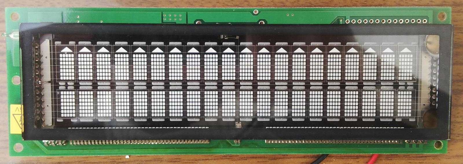
The size of the PCB is determined by the dimension of 2x20 character dot-matrix VFD display. Once upon a time, I obtained such display very cheaply and sinde then I wanted to make use of it. The module is designated M202MD08A, manufactured by Futaba:
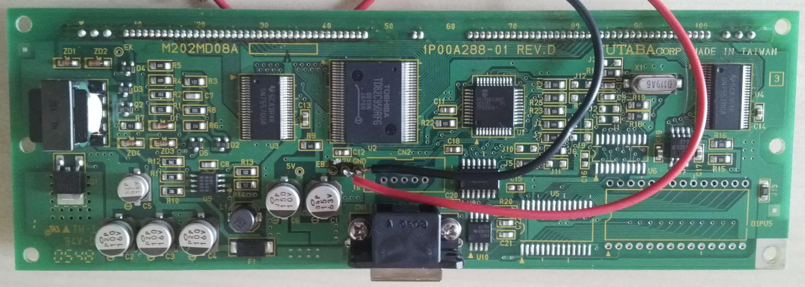
Most likely its purpose is to be a part of point of sale system. It has RJ45 connector however no documentation was available. I tried to do some reverse engineering however the attempts were spoiled by accidentally burning the on-board microcontroller.
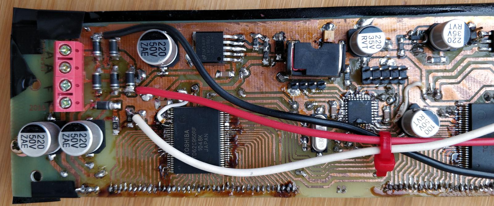
After bricking the board I decided to desolder the VFD and design a custom board for it. First I desoldered TD62C950RF driver using the heat gun. Since the VFD is a delicate component, I took extra care during the removal. I cut the PCB near the display’s pins into several pieces for easy removal before heating each piece with the heat gun. The VFD was wrapped in aluminium foil to protect it from excess heat. Having the VFD desoldered, I identified the pins using method described in my other article.
The board contained TD62C950RF which is anode driver with 40 outputs. I desoldered it too, but fearing it might be broken, I ordered two of these chips on Aliexpress. The original one was in fact fully functional, it found the new home in clock board.
The display has 40 characters, each one is 5 x 7 dot matrix. Additionally there’s line of triangle-shaped pixels above the upper row, they share the grids with its respective character. Overall, there are:
- 40 grids
- 5 x 7 + 1 anodes
- heater
which sums up to 76 drivable pins + two for filament voltage 5 V AC.
The circuit
The whole Octoglow device is powered from the mains transformer which provides two voltages: 24 V and center-tapped 5 V AC. 24 V is rectified in diode circuit combining the Graetz full bridge rectifier with voltage doubler, which produce +35 V and +50 V respectively. +50 V supplies the anodes of the displays both on this board and also clock board. +35 V available on external connector (Geiger counter board uses it), but here is down-converted to 5 V by highly popular LM2596 buck converter. +5 V is meant to be standard supply voltage but some devices need +3.3 V, so LM1117 was added to provide it.
The center tap of heater winding is connected to +5 V to provide correct polarisation of the VFD grid. When the VFD electrode is pulled down to GND, grid-cathode voltage is -5 V average, switching the pixel down for good.


The heart of the board is ATmega88A microcontroller accompanied with 16 MHz crystal and 10-pin STK200-compatible socket for in-circuit programming. Its main task is to constantly drive the dot-matrix display. This is done by specialized chip: TD62C950RF, 40-output serial-to-parallel latch and high voltage driver. It can drive loads up to 70 V which will suit any VFD. Two of them are connected in daisy chain which gives 80 outputs, the display uses 76 of them. To make the PCB layout as simple as possible, driver’s output order does not follow the order of the electrodes on the display. It was done to avoid crossings on the board. It makes the firmware a bit more complicated though.
The user interacts with the device by rotary encoder dial, which has its own connector. There are also blocks on the board no longer used: ESP-12E module (not mounted) and one-transistor amplifier for speaker connected to the PWM output of the microcontroller.

Firmware
Firmware was written in C++ (exceptions and dynamic allocation disabled) and compiled with avr-gcc. Because Clion is my IDE of choice, CMake was used instead of traditional make. The code root is firmware/front-display/. I²C slave implementation by Andreas Kaiser. The code is divided into following modules:
noarch- The application logic. By principle, hardware-agnostic and cross-compilable under x86 as well. Covered with unit tests.avr- Hardware-dependent code, intended to be as small as possible, all logic delegated tonoarch.font- 5x7 font definition created with GLCD software. This is the most common 5x7 font in XML format. I extended this set with Polish language characters. GLCD can generate C/C++ header from this XML.test- unit tests runnable under x86, written with GTest framework.
The display works in multiplex mode. The exact frequency is not definitely set because multiplexing is done in main loop, not triggered by timer. The frequency is several hundred Hz. There is global display buffer, which is constantly written on the screen. Each character has 5 columns, each stored in one byte, which gives 5 x 40 = 200 byte buffer. Various procedures of static/scrolling text or graphics modify this buffer. The font has UTF-8 support, but only Polish native characters are supported. Any unrecognised character is rendered as `⃞.
Overall, the firmware listens to I²C requests under address 0x14. There are following requests supported:
Get encoder state
Request: 1.
Response: encoder delta|button state.
| Value | Size | Description |
|---|---|---|
| encoder delta | 1 | Signed integer, how many ticks since last read. Set to zero after read. |
| button state | 1 | 1 - just pressed, 255 - just released, 0 - no change since last read. |
Encoder code was copied from this. It uses the combination of pooling and interrupt.
Set display brightness
'3'|brightness
| Value | Size | Description |
|---|---|---|
3 |
1 | Magic byte |
| brightness | 1 | From 0 (display shutdown) to 5 (max). |
Brightness is controlled by setting CL pin of TD62C950RF at the proper moment in the multiplexing loop. No hardware PWM is used.
Write static text
'4'|start|max length|zero-terminated utf8 text
| Value | Size | Description |
|---|---|---|
4 |
1 | Magic byte |
| start | 1 | Starting position of text. Between 0 and 39. |
| max length | 1 | Max length of the text. If the text is shorter, remaining place is filled with spaces. |
| text | n | Zero-terminated UTF-8 text. Only Polish characters are supported. If text is longer than the display allows, it’s truncated. |
Static text is set by directly copying the character shapes to the pixel buffer.
Write scrolling text
Scrolling text is implemented by cyclically refilling the pixel buffer with columns shifted left. There are three slots for independent text. Capacity is in bytes, co using multibyte UTF-8 characters will reduce the effective size.
| Slot | Capacity |
|---|---|
| 0 | 150 |
| 1 | 70 |
| 2 | 30 |
The command:
'5'|slot|start|length|zero terminated text
| Value | Size | Description |
|---|---|---|
5 |
1 | Magic byte. |
| slot | 1 | Slot number. |
| start | 1 | Starting position of text. Between 0 and 39. |
| length | 1 | Length of the text window. Length + start position cannot exceed 39. |
| text | n | Zero-terminated UTF-8 text, max length depends on the slot. |
Draw graphics
It is also possible to load arbitrary data to pixel buffer. This feature is used when drawing charts.
6|start|length|sum with text|column bytes
| Value | Size | Description |
|---|---|---|
| 6 | 1 | Magic byte. |
| start | 1 | Starting column. |
| length | 1 | Number of columns. |
| sum with text | 1 | 1 - when sum with existing content. 0 otherwise. |
| column bytes | n | Content. Youngest bit is associated with uppermost pixel. |
Set upper bar content
The pixel bar above the characters acts as progress bar. To set its content:
7|content
| Value | Size | Description |
|---|---|---|
7 |
1 | Magic byte. |
| content | 4 | Content of the bar. Youngest bit is the leftmost pixel. |
Clear display
'2'
Sets the display content to empty. Clears all buffers.