
Wall time is the most important information which Octoglow should provide, it is reasonable to have separate display for it. Having this in mind, the design principles shifted to more complicated contraption, having multiple boards and bigger enclosure. Octagonal steel chassis was devised at this time. The new board itself features the following:
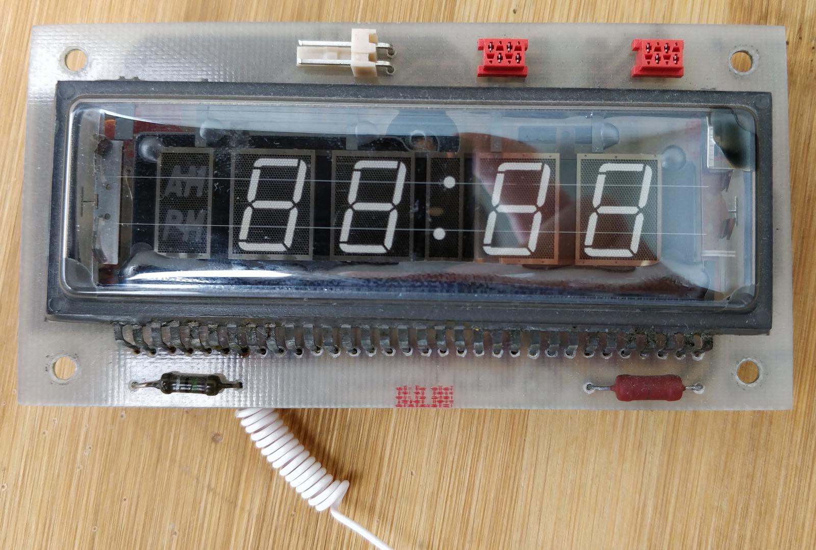
- 4-digit numerical display for current wall time.
- 433.92 MHz ASK/OOK receiver to receive temperature and humidity data from remote weather sensors.
- Two relays to drive auxiliary loads.
One of them is actually used, it drives telephone bell installed on the frame.Since the bell has been removed, relays stay unused for now.
Update May 2021: Octoglow was rebuilt, some changes where made: the bell was removed, pair of speaker were installed instead, they are driven from Orange Pi’s audio output. BIOWIN weather sensor was replaced by two Fanju radio sensors, software was modified accordingly. Old info stays for reference.
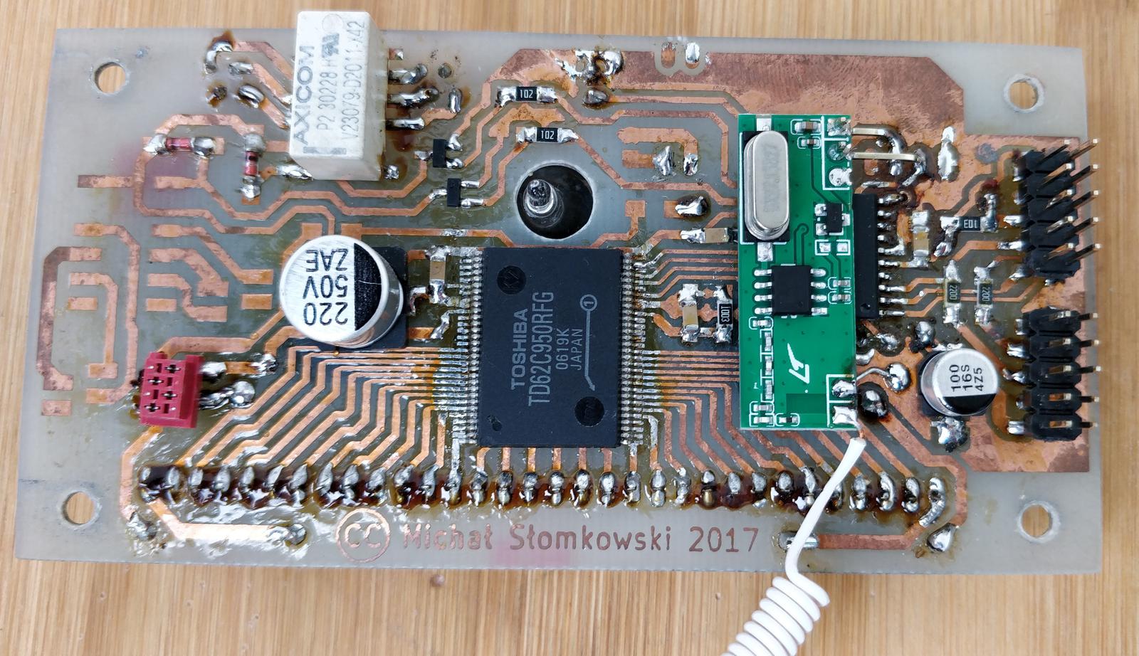
PCB layout was designed in KiCad, all project files are located in pcb/clock-display/. The heart of the board is ATtiny461A microcontroller which acts as I²C slave on the system bus. It interprets the packets from 433.92 MHz receiver, controls the relays and sends the appropriate content to the VFD driver. There are following connectors on the board:
- 10-pin system bus
- 10-pin STK200 ISP header
- female Micro-MaTch for +35 V anode voltage and filament power
- four female Micro-MaTch’s for relays
Micro-MaTch are not popular, but they were chosen because of the compactness and overall good look. It was important to me because the board’s front side was meant to be exposed, housing prominent filament resistors and relay connectors.
The VFD itself is salvaged from the pile of scrap electronics I found at the roadside when I was riding my bike. I took the weathered PCB home and examined the display. I was undamaged! I decided to give it a new life and purpose.
The display is quite unusual because it is not multiplexed. Every anode has its own pin and all grids are connected together - multiplexing is not possible in this setup. Overall, there are 30 pins to drive. I again used chip TD62C950RF which successfully works in main display. The grid is driven by TD62C950RF output, but in firmware it is effectively pulled high. The brightness is varied by driving CL ping by ATTiny’s TIMER 1 PWM output. Filament voltage is ~3 V, I used the method described in my other article to find proper values for resistors R8 and R10.
The original 433.92 MHz receiver module was RFM83C-433S (as seen in the schematic), but the performance was rather low, I later replaced it with pin-incompatible RFM210LCF-433D-A. The antenna is made of copper wire as shown on Instructables. Receiver’s output drives the ATTiny’s interrupt line. The protocol and the decoding algorithm is described below.
Relay driving circuit is straightforward. One relay is unused, the other switches the telephone bell. The bell is powered directly from supply transformer’s 24 V AC. In the telephone line, 25 Hz usually is used, but 50 Hz still does its job (for your information, mains power in continental Europe is 230 V 50 Hz). The ringing sound is almost indistinguishable from classic telephone ring. Telephone bell was removed, because updated Octoglow contains speakers with amplifier.


Two-pin header on the front side was meant as 1-Wire interface, but eventually it was left unused. There is also unused pin with PWM output meant for driving analog gauge meter.

Firmware
The code follows the same principle as for the main display; its root under firmware/clock-display/. It is quite simple, the only not-so-trivial routine is decoding data from receiver module. In its main loop, the software receives commands from I²C on address 0x10 and acts accordingly. It supports following requests:
Set display content
The display has four digits and separator dots.
'1'|digit 1|digit 2|digit 3|digit 4|dots
| Value | Size | Description |
|---|---|---|
1 |
1 | Magic byte |
| digit 1 | 1 | ASCII-encoded digit, leftmost. |
| digit 2 | 1 | |
| digit 3 | 1 | |
| digit 4 | 1 | |
| dots | 1 | Bitwise OR for display dots: 0-th bit = lower dot, 1-st bit = upper dot. |
Set relay state
'2'|relay 1|relay 2
| Value | Size | Description |
|---|---|---|
2 |
1 | Magic byte |
| relay 1 | 1 | 1 - switched on, 0 - switched off. |
| relay 2 | 1 |
Set display brightness
'3'|brightness
| Value | Size | Description |
|---|---|---|
3 |
1 | Magic byte |
| brightness | 1 | From 0 (display shutdown) to 5 (max). |
Get weather sensor data
The only read request. To trigger read, send 4 to the device, then read response:
flags|raw data
| Value | Size | Description |
|---|---|---|
| flags | 1 | Valid measurement = 0x2, already read = 0x4. |
| raw data | 5 | Raw data (40 bits) from weather sensor. Contains sensor channel number. Needs to be decoded. |
Weather sensor protocol - Fanju SP67
My new weather sensor is branded Fanju, designated SP67. I found out that someone had already reverse-engineered the protocol used by this sensor. Transmission is OOK-modulated. Receiver puts demodulated signal at its output, which I recorded using sound card. Sample message, shown in the screenshot:
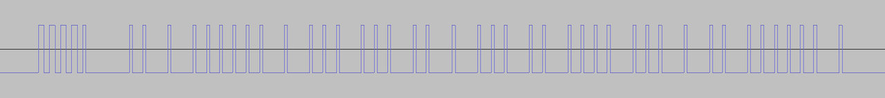
Message starts with four pulses of carrier followed by 8 ms of carrier. This is done to adjust the AGC in the receiver. Then 40 bits of data encoded as:
- 2 ms pulse -
0, - 4 ms pulse -
1.
The payload includes checksum, which is calculated with algorithm which is published on aforementioned website. I myself reimplemented it in Kotlin in octoglowd daemon.
| Bit | Length | Function |
|---|---|---|
| 12 | 1 | 1 - transmission forced by TX button, 0 - automatic transmission. |
| 13 | 1 | 0 - battery OK, 1 - weak battery. |
| 16-27 | 12 | Temperature value, big endian. Formula to calculate deg C below. |
| 28-35 | 8 | Humidity in %, BCD encoded. |
| 38-39 | 2 | Channel selected by switch: 00 - 1, 01 - 2, 10 - 3. |
temperature = (temperatureBits - 1220.0) * 1.0 / 18.0
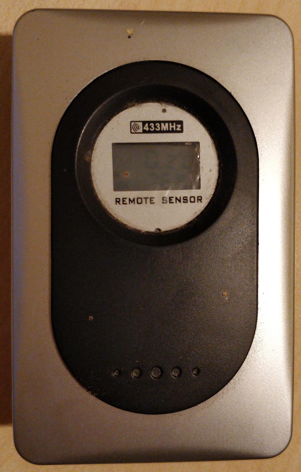
Old weather sensor protocol - Biowin
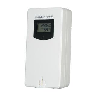
This sensor I used previously, labeled BIOWIN BIOTERM, is shown in the photos. I reverse-engineered the protocol by connecting the receiver’s output to PC sound card and analysing the signal with Audacity. The process is described in detail in many articles on the web, for example here.


The protocol description
Weather sensor sends its OOK-modulated data at 433.92 MHz. A couple of packets are sent every minute, less often when battery is almost depleted. Each transmission starts with several impulses to set the Automatic Gain Control in the receiver. Then, following rules apply:
- start bit: ~9 ms of carrier
1data bit: ~4 ms0data bit: ~2 ms
Each single packet consists of:
- start bit
- 36 data bits
- stop bit - valued
0
and has following structure:
| Bit | Length | Function |
|---|---|---|
| 0-3 | 4 | Always value 9. |
| 4-11 | 8 | Random number generated at power-on. |
| 12 | 1 | 0 - battery OK, 1 - weak battery. |
| 13 | 1 | 1 - transmission forced by TEST button, 0 - automatic transmission. |
| 14-15 | ² | Address selected by switch: 00 - 1, 01 - 2, 10 - 3. |
| 16-27 | 12 | Temperature in 0.1 deg C. Signed, two’s complement. |
| 28-35 | 8 | Humidity in %. |
Decoding
The core of the algorithm is implemented in source file src/receiver433.cpp. Since this is legacy code, I tagged it in repository as biowin-weather-sensor.
Receiver is connected to hardware interrupt INT0 and each rising edge triggers the interrupt service routine. TIMER 0 is configured as counter, its purpose is to measure time between the subsequent interrupt calls. Interrupt service routine checks the time elapsed from its previous execution: if it is 4 ms +- 5%, 1 is saved to the packet buffer and the buffer is shifted left. Accordingly, when 2 ms +- 5%, 0 is saved. Other intervals are invalid and the buffer is cleared in this case.
As 36 bits are loaded, the content of the buffer is copied to spare buffer. The idea is to receive the identical packet once again. If their content match, the packet is assumed valid and appropriate fields in structure WeatherSensorState are set among with the flag new measurement ready.
TIMER1, which is used by the display to generate PWM signal, has also interrupt configured to fire in order to implement timeouts. When the timeout fires, the buffer is reset. This is done to reset the state machine in case of partially received packet.