Since building things is fun, I built myself a paragliding helmet instead of buying one. I saved some money too! I used a generic skateboard helmet with Peltor earmuffs fitted with communication equipment. I was heavily inspired by the helmet made by SP3OTZ (his website is no longer functional). I have taken plenty of photos, so the construction details are clearly visible.
The headset works with Baofeng UV-5R and my Kobo BlueFly variometer. After almost two years of intensive use, I can tell that the receiving voice quality and noise muffling are excellent. The modulation is loud and clear, but at full throttle, it becomes almost unintelligible because of the noise generated by ignition. This might be fixed in the future by trying to shield the ignition cable in my paramotor.
To make a high-quality communication set, you need high-quality speakers, microphones, and mechanical components. The best source for them is military surplus shops. They have plenty of military and aviation headsets at cheap prices, which also have rugged microphone arms.
Update April 2020: The article now includes a new microphone circuit schematic and extended information about voice transducers. The photos have been remade to include the changes.
Integrating voice equipment into Peltor earmuffs
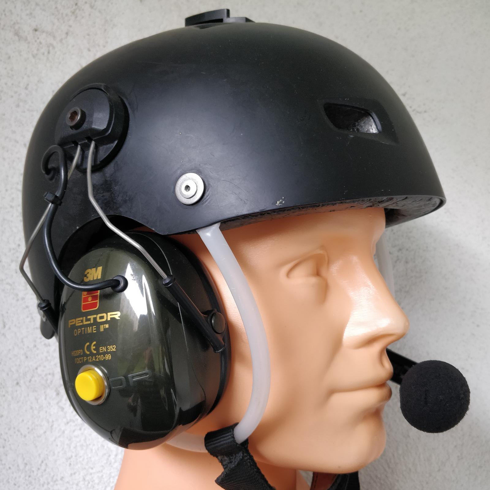
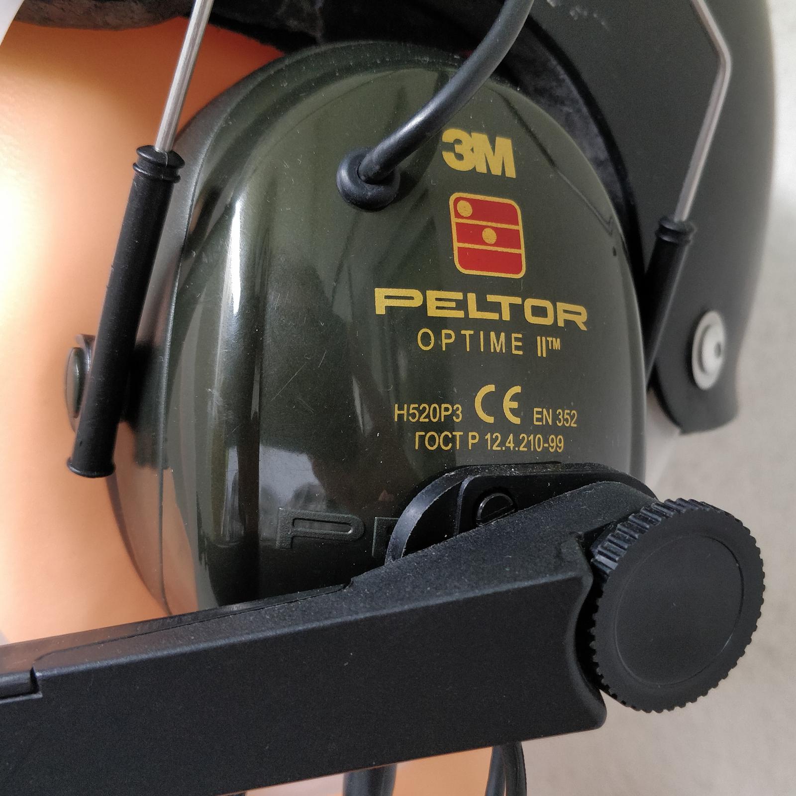
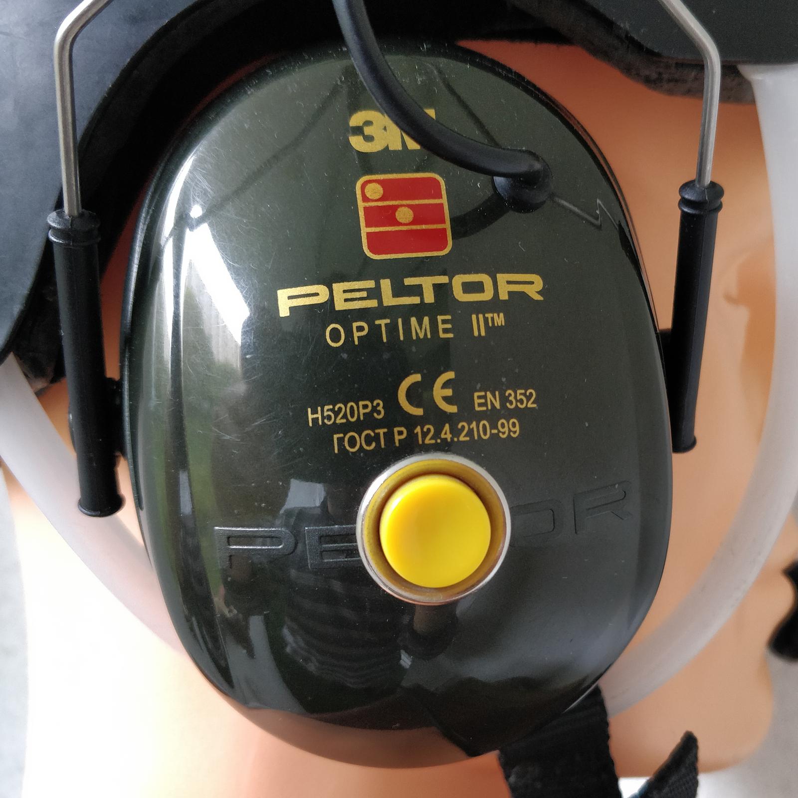
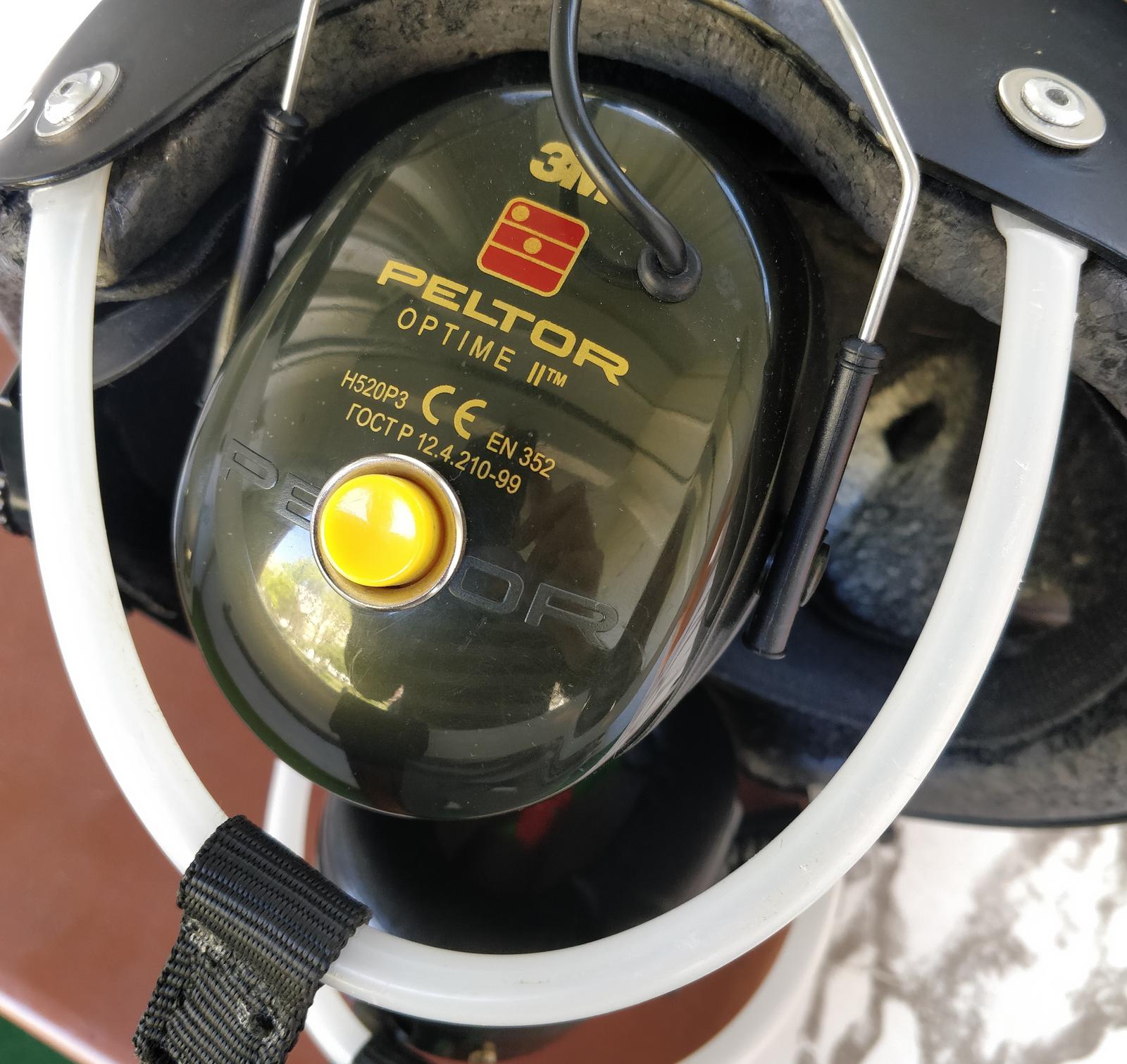
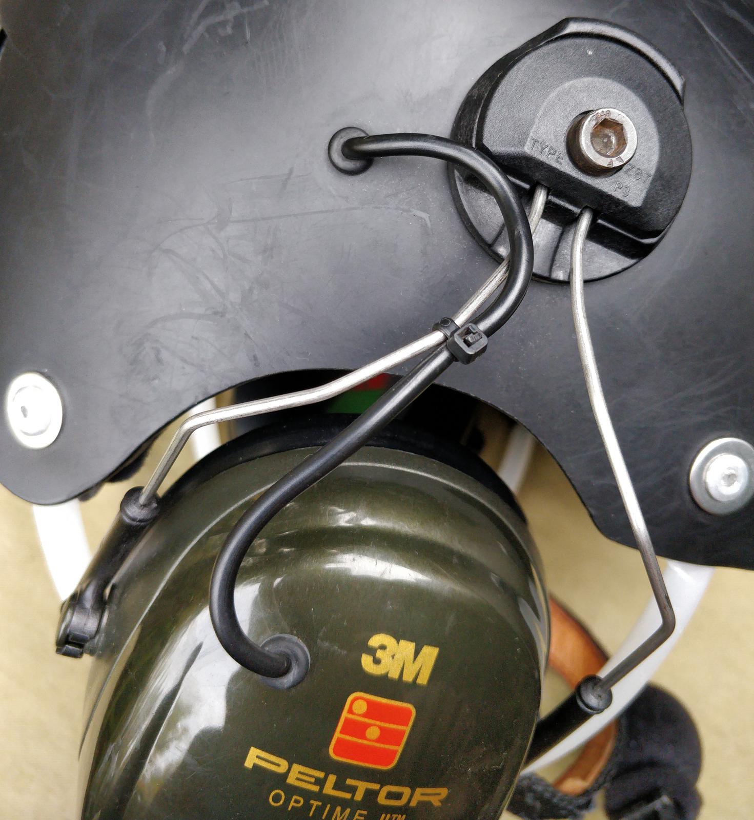
The base for the headset consists of a pair of Peltor Optime II ear defenders with attachments suitable for hard hat mounting. They provide ample space inside and, according to the manufacturer, reduce noise by 31 dB, which is more than sufficient. If you require even more noise reduction and internal space, consider using Peltor Optime III.
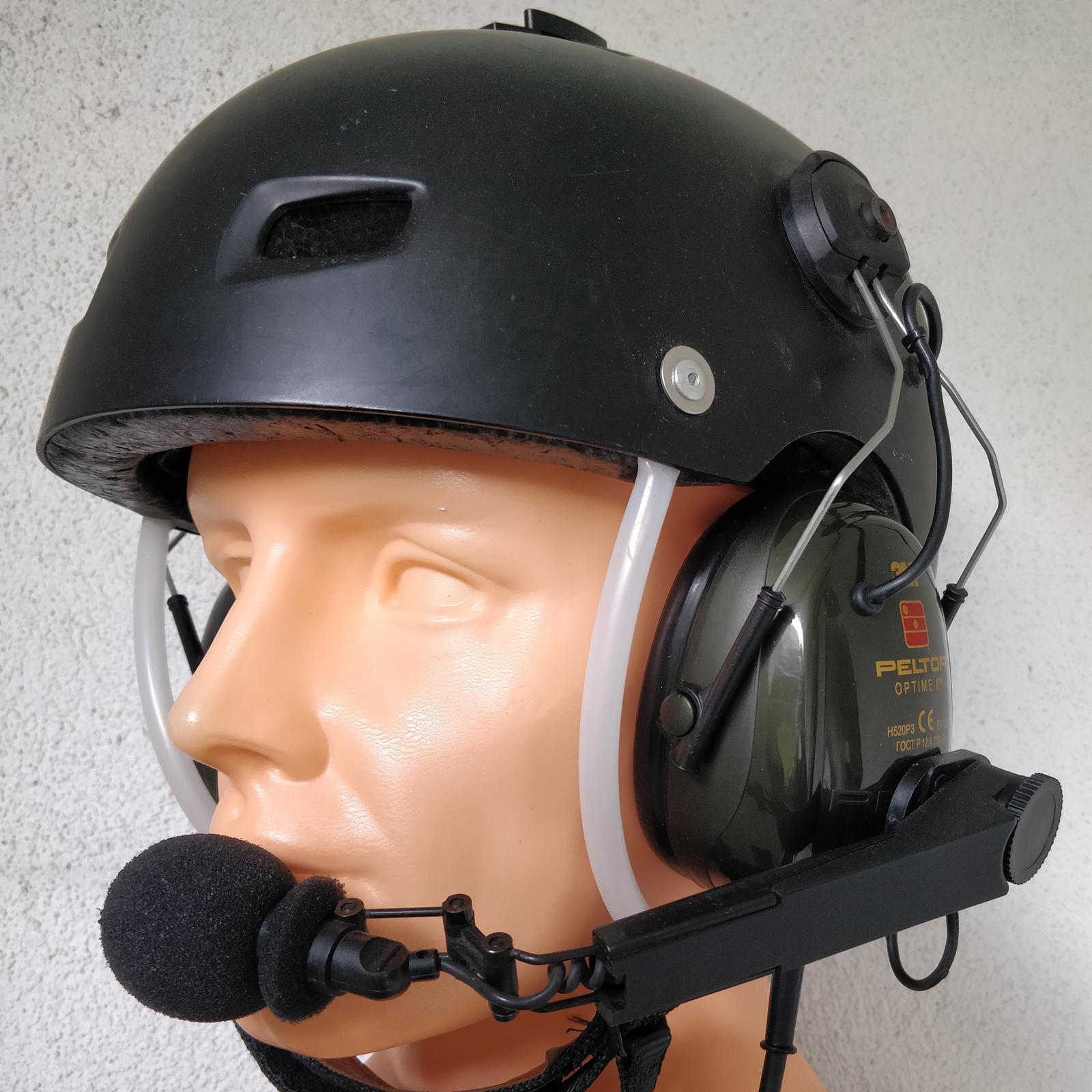
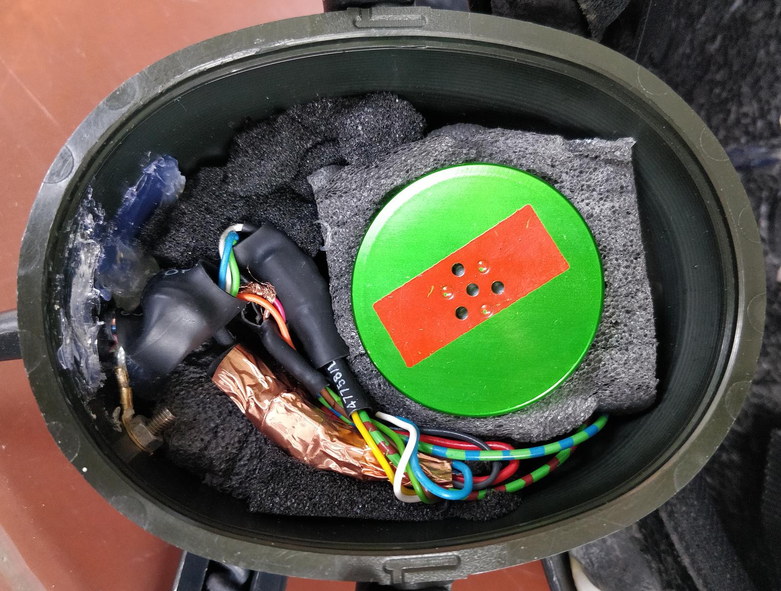
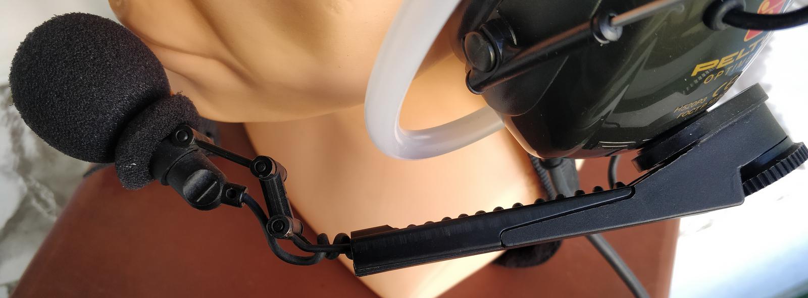
The Push-To-Talk (PTT) button is located on the right earmuff. Since I have the throttle in my left hand, it feels natural to press the PTT button with my other hand. The cable and microphone arm are attached to the opposite earmuff. The earmuffs are connected by a four-wire cable, which runs through the groove etched in the helmet’s inner shell, encircling the head. Two wires are used for the PTT button, while the other two for the right earphone. I incorporated cable grommets to protect the cables from vibrations and to achieve a professional appearance.
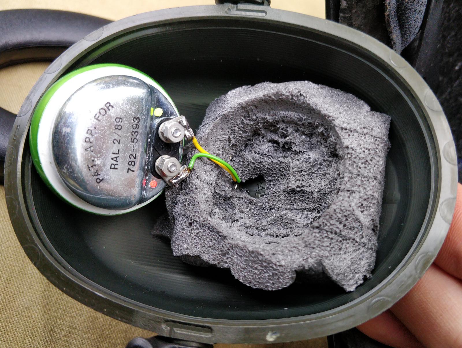
The stock earmuff contains soft foam. I cut and removed a part of the foam to accommodate the transducers. To secure the earphone in place, I used a piece of hard foam cut in the shape of the earphone.

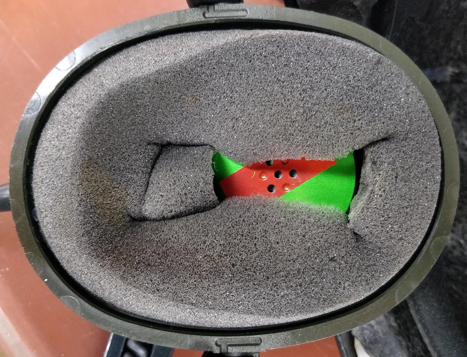
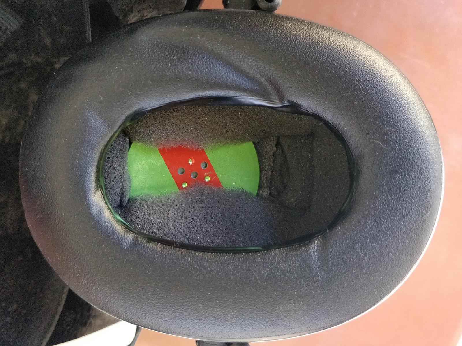
Earphone transducer
A good transducer for paramotoring should be rugged and capable of accurately reproducing the spectrum of human voice while damping other frequencies. I purchased a pair of military-grade speakers, specifically the Racal 782-5393, commonly used in Clansman radio equipment. Not much information is available, but I managed to find the following parameters:
| Parameter: | Value: |
|---|---|
| DMC | Z42 |
| P/NO | 27187-11 |
| Impedance | 300 Ω |
EM-1 and EM-2 headphones are extremely similar to my headpiece, but mine has different painting: green with red flash.
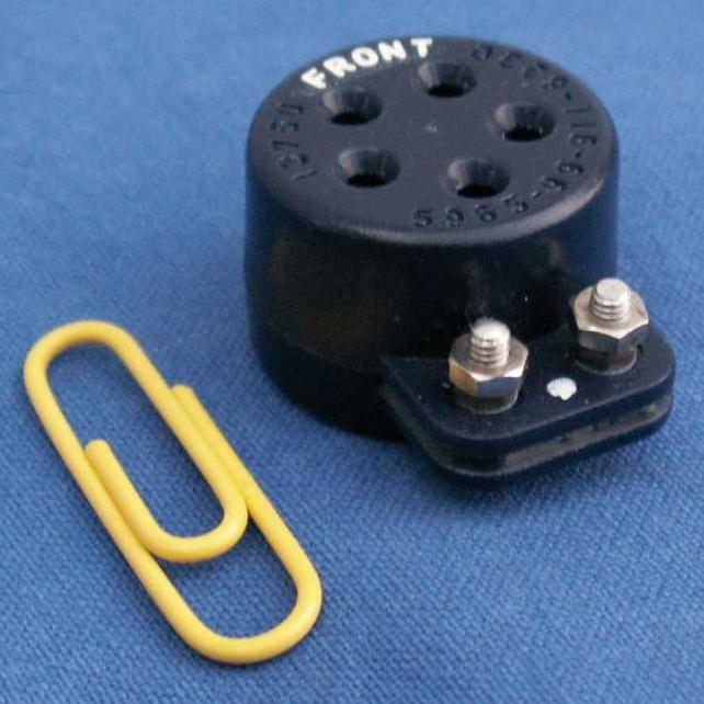
Microphone
The microphone I used was the Racal Acoustics 13750, also known as 5965-99-911-8230. It is a differential microphone designed to be used in noisy environments, similar to the Russian DMSZ1. I purchased it at a military surplus store along with the speakers. Although I couldn’t find the datasheet, I gathered all useful information from the Eylex tank helmet brochure, which includes parameters of the Racal 13750 and other military microphones. Here is an overview of the device:
| Parameter: | Value: |
|---|---|
| Part NO. | 13750 |
| NSN NO. | 5965-99-911-8230 |
| Transducer Type | tropicalised noise cancelling magnetic microphone |
| Sensitivity | -65 dB re 1 V/Pa at 1kHz with sound source 9.5 mm distant from front of microphone. The peak output is approx. 3 mV for loud speech close to the microphone. |
| Impedance | 300 Ω ± 20% at 1 kHz. |
| Noise cancellation | Approx. 35 dB at 100 Hz gradually reducing to 0 dB at 1.2 kHz. Other spec says: approximately 20 dB at low frequencies, reducing in effect as the frequency increases and reverting to normal pressure operation at 3.2 kHz. |

… and its frequency response chart (output in dBV/Pa):

Microphone amplifier module and wiring
The Racal microphone has comparably low sensitivity (-65 dBV/Pa), whereas most analog electret and MEMS microphones have sensitivity between -46 dBV/Pa and -35 dBV/Pa. The signal from the microphone is too weak to drive the Baofeng directly, making an amplifier with a gain of 15 to 20 dB essential.
Initially, I tested the integrated amplifier SSM2167, which also has a built-in compressor. However, its input noise gate has too little sensitivity (approximately -55 dBV) to reliably open when I am talking. This resulted in heavily distorted speech.
Finally, I opted for the MAX9812L module, which is widely available on AliExpress or eBay. In fact, there are several modules available, shown in the photos:
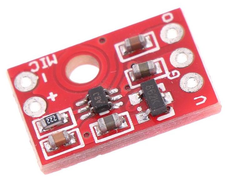

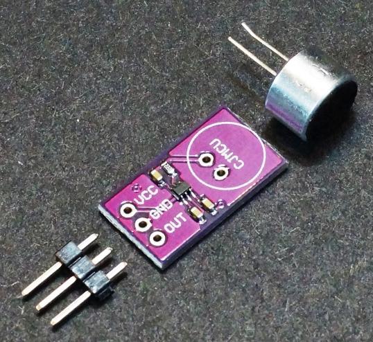
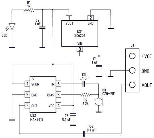
The bare MAX9812L can be supplied with a voltage in range of 2.7 - 3.6 V. The first two modules feature the voltage stabilizer XC6206, which enables them to be powered from a 3 - 5 V supply. Both modules have nearly identical schematics, each representing the basic application of the MAX9812L with a low-drop stabilizer.
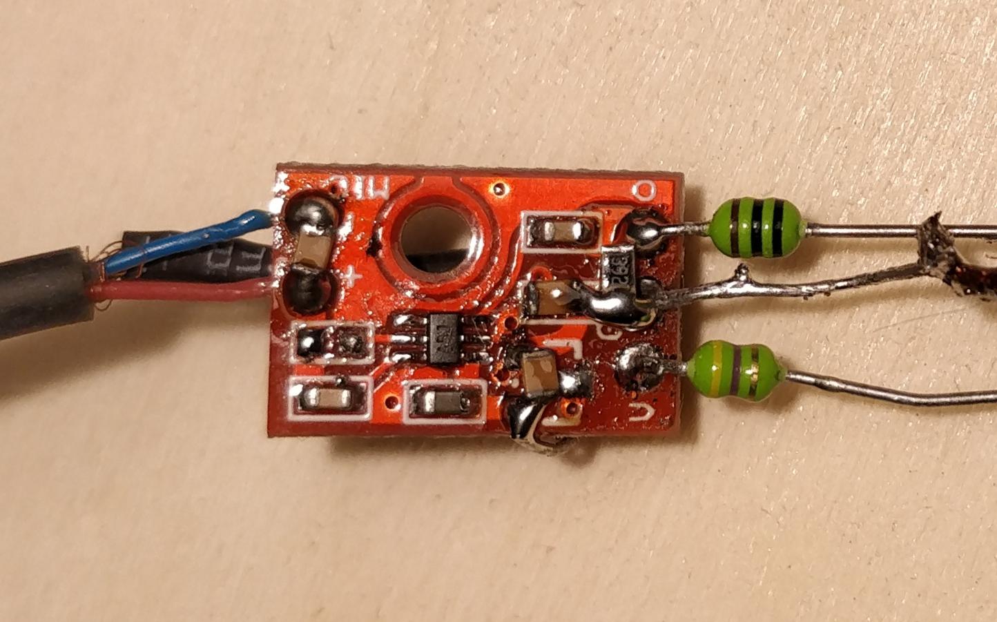
Off-the-shelf module acquired from AliExpress was modified in the following manner, with the process illustrated by the photos:
- Removal of resistor R2 (2.2 kΩ)
- Removal and bypass of voltage stabilizer XC6206
- Addition of a 1 nF capacitor between the input and GND
- Addition of a 1 nF capacitor and a 3.9 kΩ resistor between the output and GND
- Addition of a 1 nF capacitor and a 4.7 μF capacitor between 3.3 V and GND
- Installation of 4.7 μH chokes on the output and 3.3 V lines
- The entire board was shielded with copper tape.
The complete schematic of the headset:

The headset is powered through a multi-wire headphone cable, which has shielding on the microphone line. At the end of the cable, two plugs are fixed: one goes to the Baofeng radio, and the other goes to the variometer. The Baofeng radio uses a Kenwood-compatible composite plug consisting of 2.5 mm and 3.5 mm jack plugs spaced 12 mm apart. The speaker signals from both devices are connected to the speakers through protection resistors R1 and R3. Capacitor C8 is intended to reduce noise from the ignition system. In my particular circuit, the variometer has an optimal volume when R1 = 47 Ω.
Great consideration was put into reducing RF and ignition noise. The antenna is in close proximity to the headphone cable, so it picks up a significant amount of RF energy. To mitigate this, I added capacitors and chokes to reduce the effect of RF power on the MAX9812L amplifier. The cable from the microphone to the amplifier needs to be shielded, preferably made of two wires with external shielding, with the shield grounded at the amplifier’s side. Although shielding is not critical in other areas, I wrapped the entire PCB in copper adhesive tape nonetheless. I also added a ferrite core extracted from a computer PSU on the main cable where it enters the shell hoping it will reduce noise.
The amplifier itself is a basic application of the MAX9812L, enhanced with RF-blocking capacitors of 1 nF (C1 and C5) and 4.7 μH chokes (L1 and L2). Without them, my circuit was overdriven by RF and remained silent. R2 pulls the radio’s input bias voltage to ~2 V. Without R2, the input stays at 3.3 V, which causes speech distortion.
Please note that this circuit requires modification of the Baofeng radio to work, as the microphone amplifier requires a constant 3.3 V power. The easy modification is described in other article.
Sourcing the cable and Kenwood plug
The most problematic part to find is the Kenwood plug, which consists of two jacks: 2.5 mm and 3.5 mm, spaced 12 mm apart. The best course of action to obtain it is to buy a handheld microphone for Baofeng, as they are typically inexpensive. However, the majority of handheld microphones use 4-wire cables, but for our purposes, we need five wires. Five-wire cables are commonly used in dual-PTT microphones. The microphone which has dual Push-To-Talk and uses five wires is shown in the photo:
For reference, I include the cable colors in this particular microphone:
| Color: | Connector: |
|---|---|
| green | 2.5 tip |
| red | 3.5 ring |
| yellow | 3.5 sleeve |
| black | 3.5 tip |
| blue | 2.5 sleeve |
My cable is made up of three pieces of cabling: a high-quality headset cable with shielded wires, approximately 70 cm in length; a Baofeng plug with a short piece of cable; and approximately 70 cm of shielded audio wire terminated with a right-angled mini jack plug, which goes to the vario. A ferrite bead is placed on the cable’s end inside the earmuff.


Old electrical wiring
From 2016 to 2019, I was using a one-transistor microphone amplifier. However, it was too quiet. I am providing the old schematic for reference. It might suit you if your microphone has better efficiency than mine.

Modifying the stock skateboard helmet
Warning! The manufacturer forbids modification of the helmet because it might lower its protection capabilities. You have been warned!
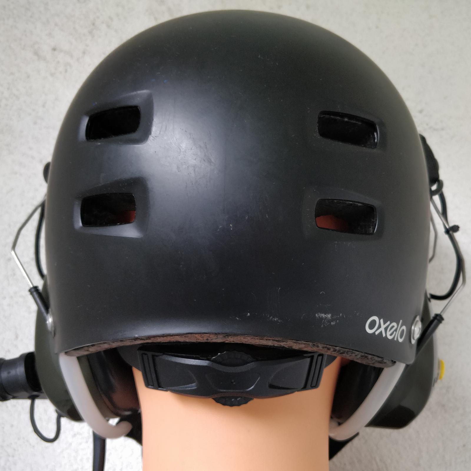
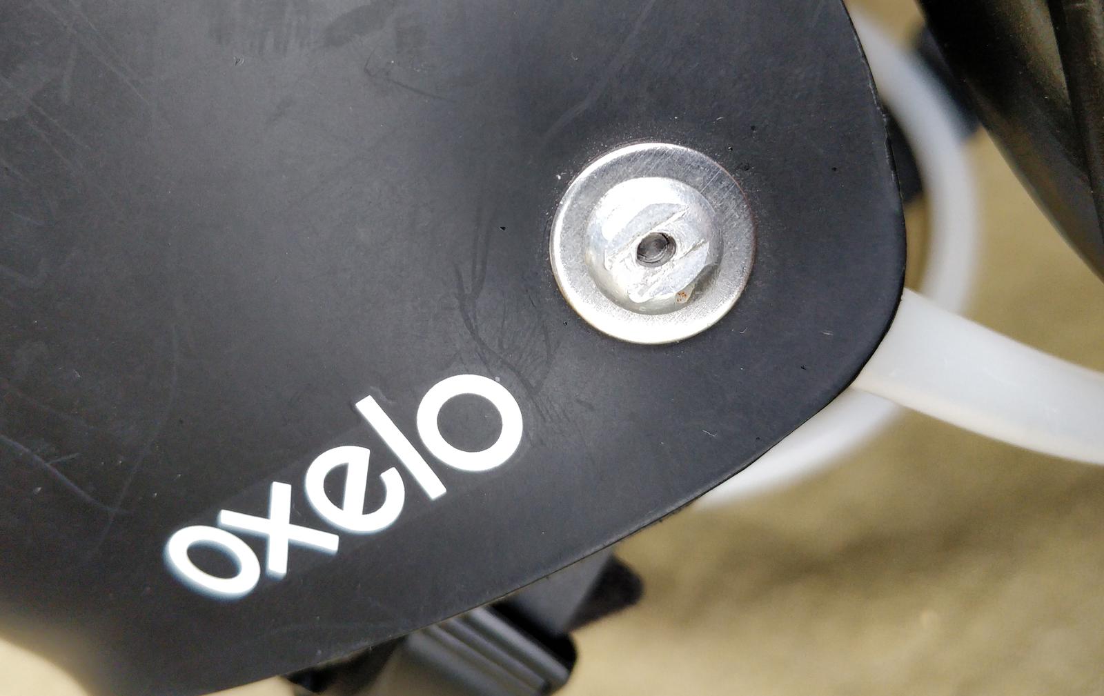
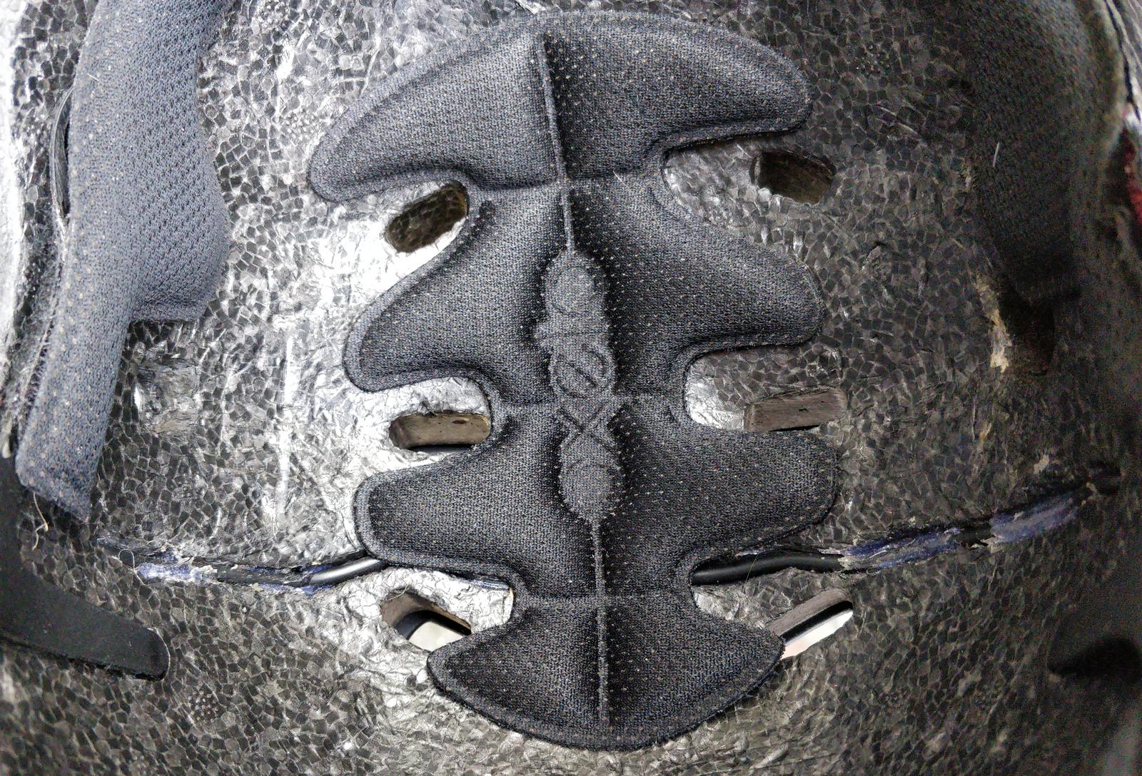
The helmet is a basic skateboarding helmet of the Oxelo brand, bought at Decathlon. A piece of the outer shell with styrofoam underneath was cut to accommodate the earmuffs. The exact change is visible when you compare my helmet with the vanilla one.


I followed the advice of SP3OTZ. The cutting procedure is as follows: first, I covered the side of the helmet with masking tape to make it easy to draw on using a pen. Then, I put the helmet on in front of the mirror and determined the optimal position of the earmuffs. I marked spots for mounting holes and drew a shape that roughly followed the shape of the earmuff with a play of 15 mm. The shape was mirrored on the other side. Next, I used a Dremel multi-tool to cut the shell and polished the edges with sandpaper, starting with 150 grit and finishing with 400 grit.
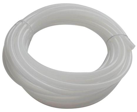
Since I couldn’t use the original helmet straps due to the earmuffs colliding with them, I opted for a different solution. I fixed 10 mm hard polyethylene tubing to go around the earmuff. This is a common solution in other paramotor helmets and provides rigidity while fitting nicely around the earmuff. I cut the tubing to the proper length and then heated the ends with a heat gun to soften them. Once softened, I easily flattened them using clamps. Afterward, I drilled 5 mm holes in the flattened ends and riveted them to the helmet’s outer shell.
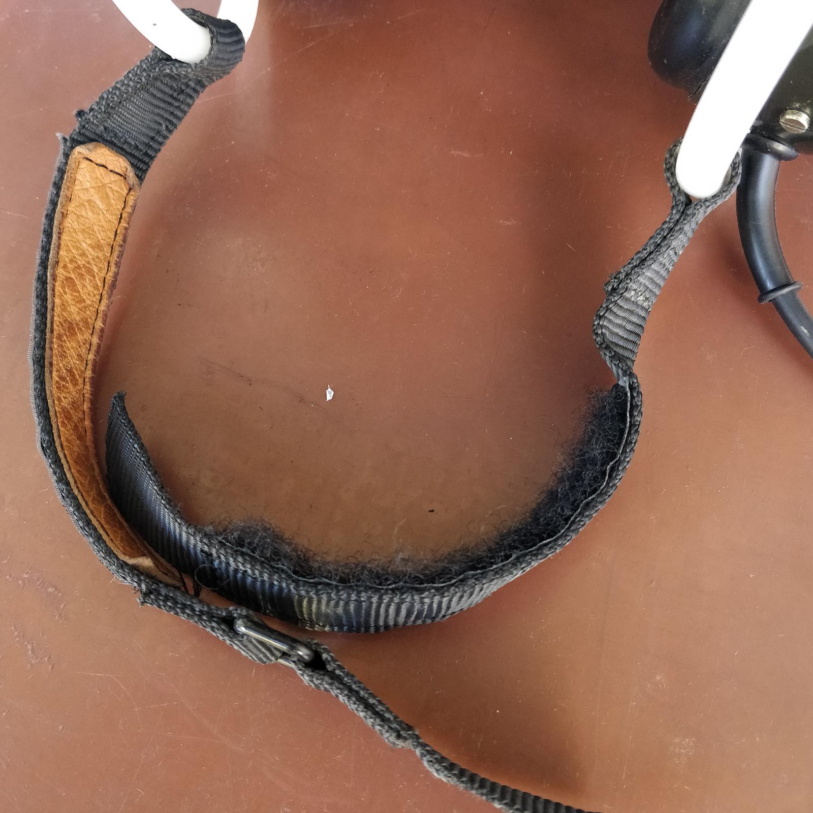
The new strap is made from pieces of Velcro strap salvaged from a military headset. Despite being Velcro, it holds better than the original plastic clip strap.
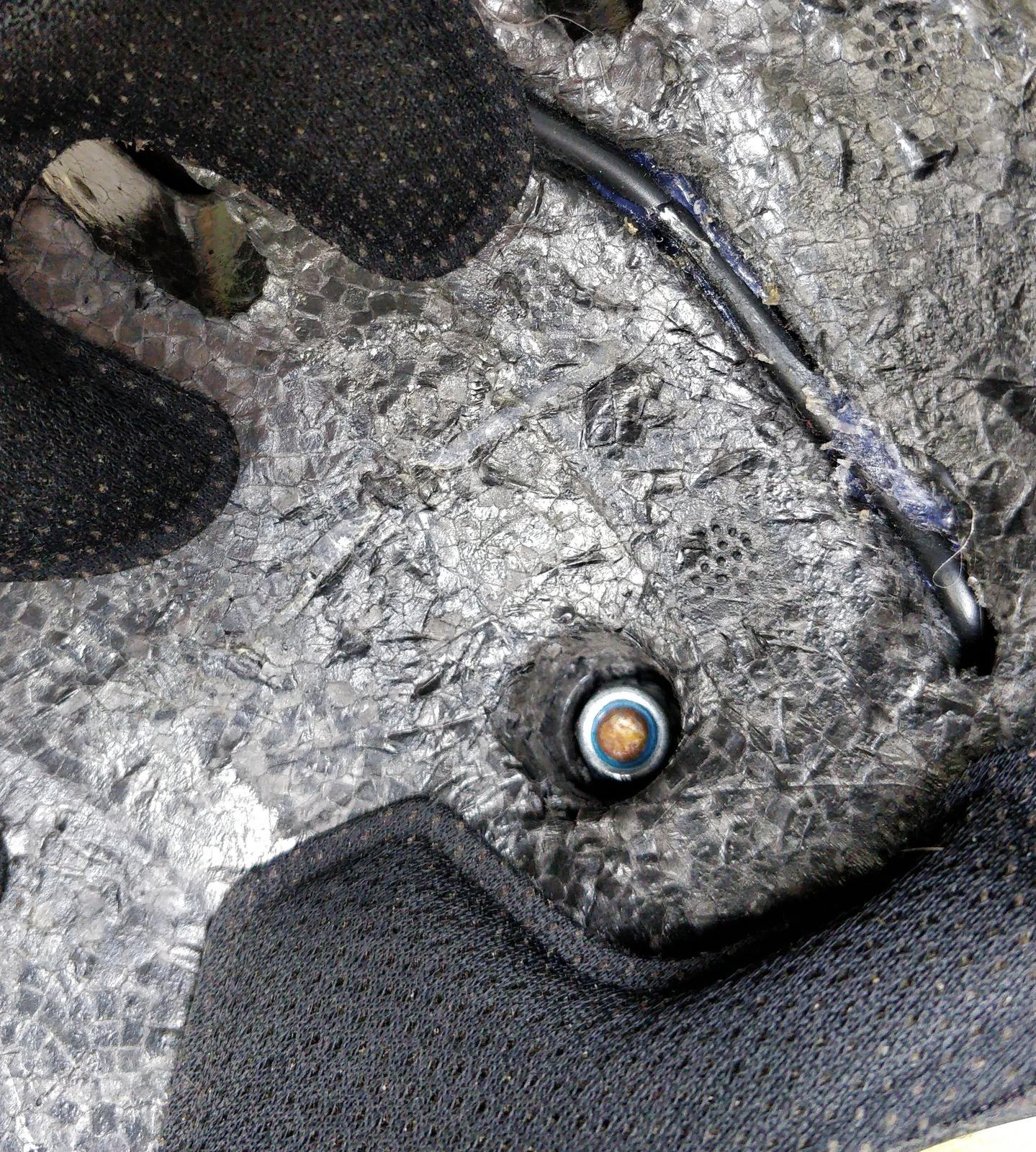
The cable connecting the earmuffs goes inside the shell and is glued to the inner styrofoam. Wherever it goes outside, it is secured by 6 mm grommets. The earmuffs are fastened to the outer shell using M6 screws and nylon locknuts. It is important that the screws are as short as possible to avoid penetrating your skull during a potential impact!
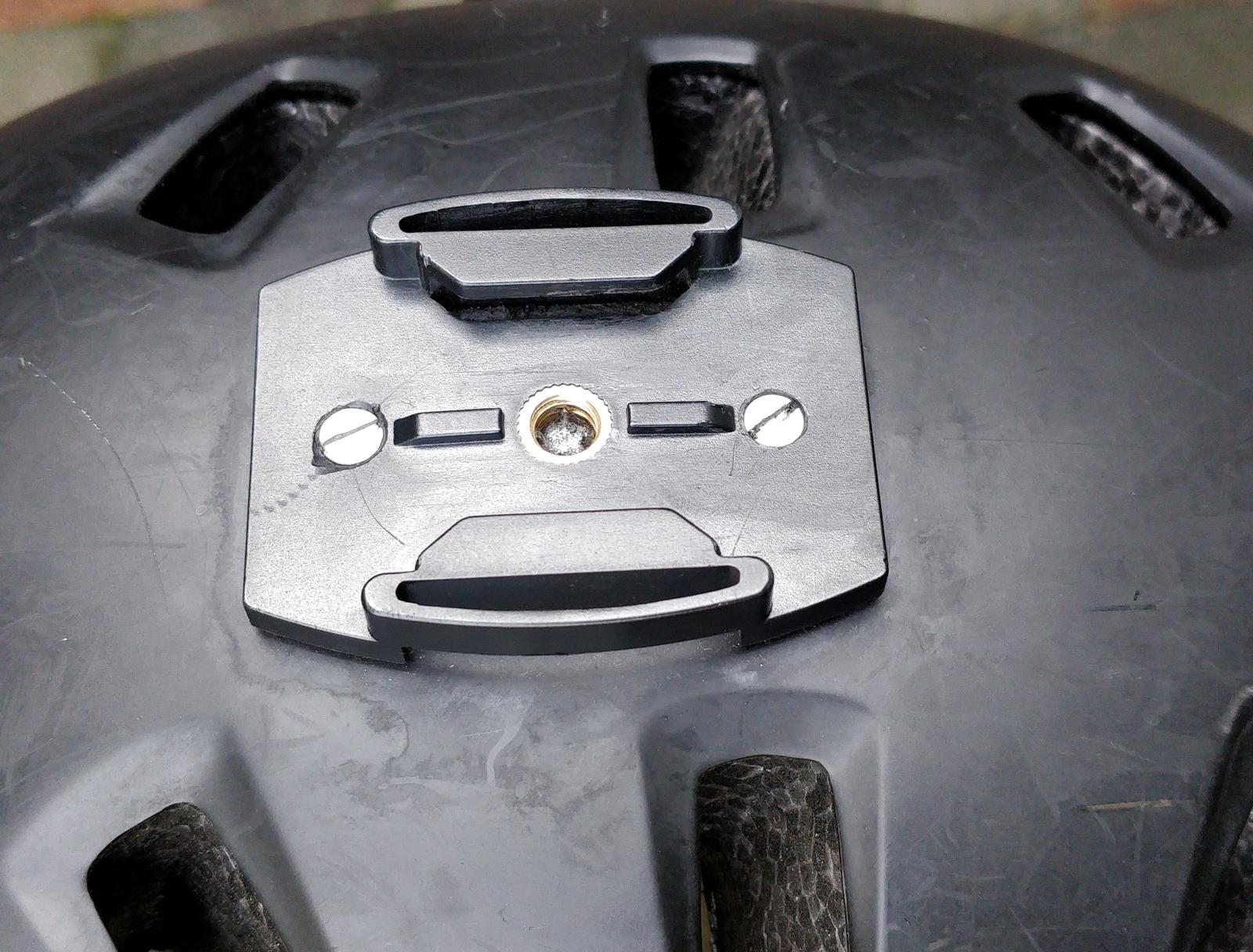
As a finishing touch, I attached a camera mount compatible with Chinese action cameras: