
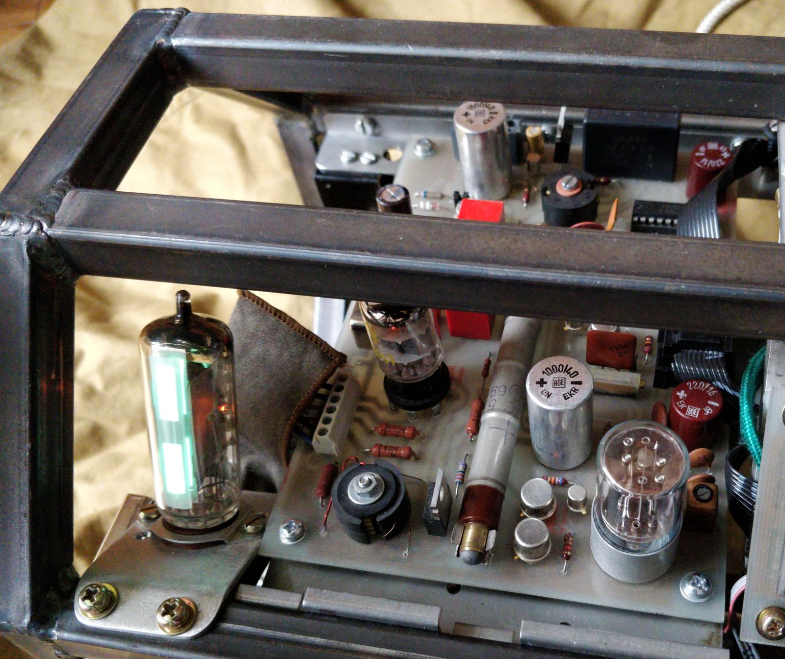
Fallout-inspired device should have something to do with ionising radiation, shouldn’t it? Therefore genuine and functional Geiger-Müller counter, sensitive to gamma radiation. It would also be nice to have some visualisation of incoming gamma particles. What can be more old-school than the mysterious glow of magic eye tube?
Designing this board I had an explicit goal to include as many strange and vintage components as possible. This resulted in crazy mishmash of components which manufacture dates span over sixty years apart.
The design process turned out to be painful. Problematic boost converters, voltage spikes roaming the board, problems with I²C resulted reiteration of the design on the new PCB. Additional learning curve was MSP430, which was completely new to me.
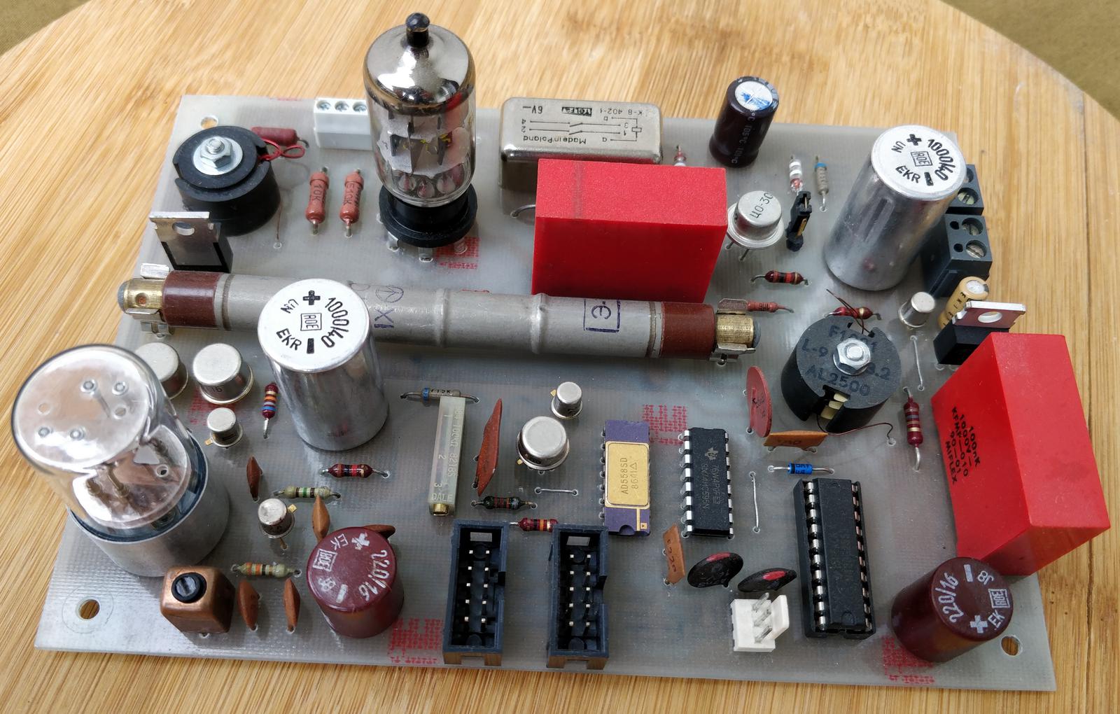
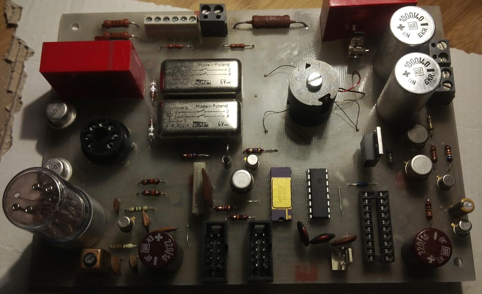
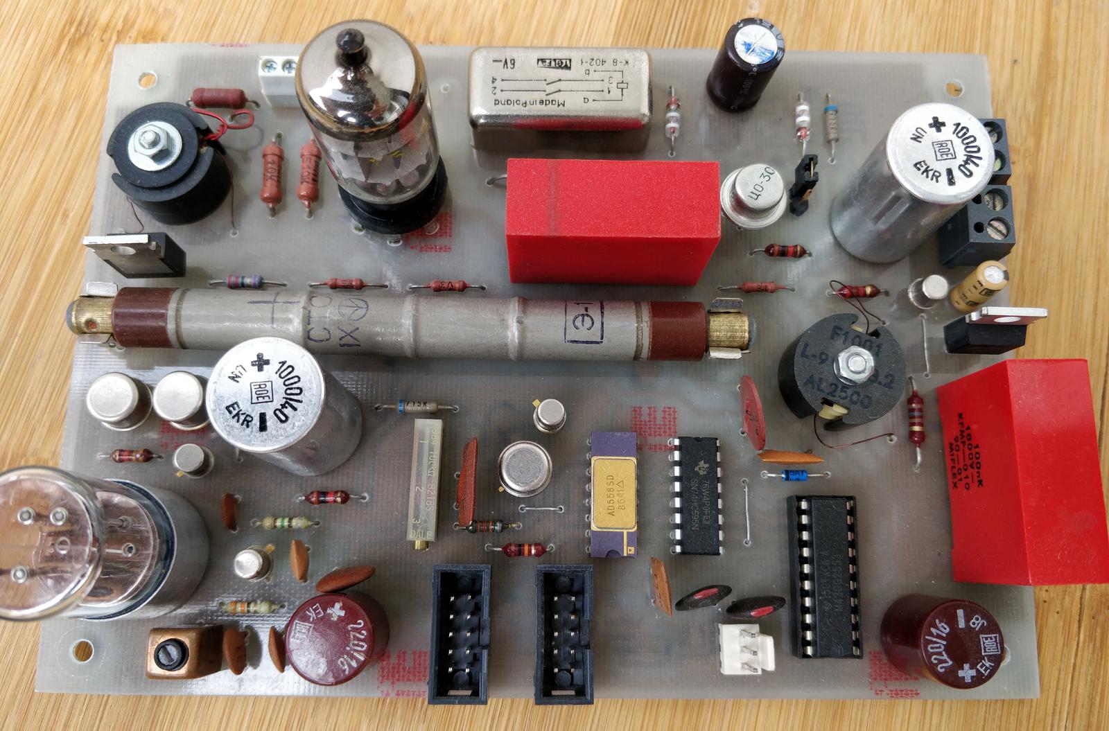
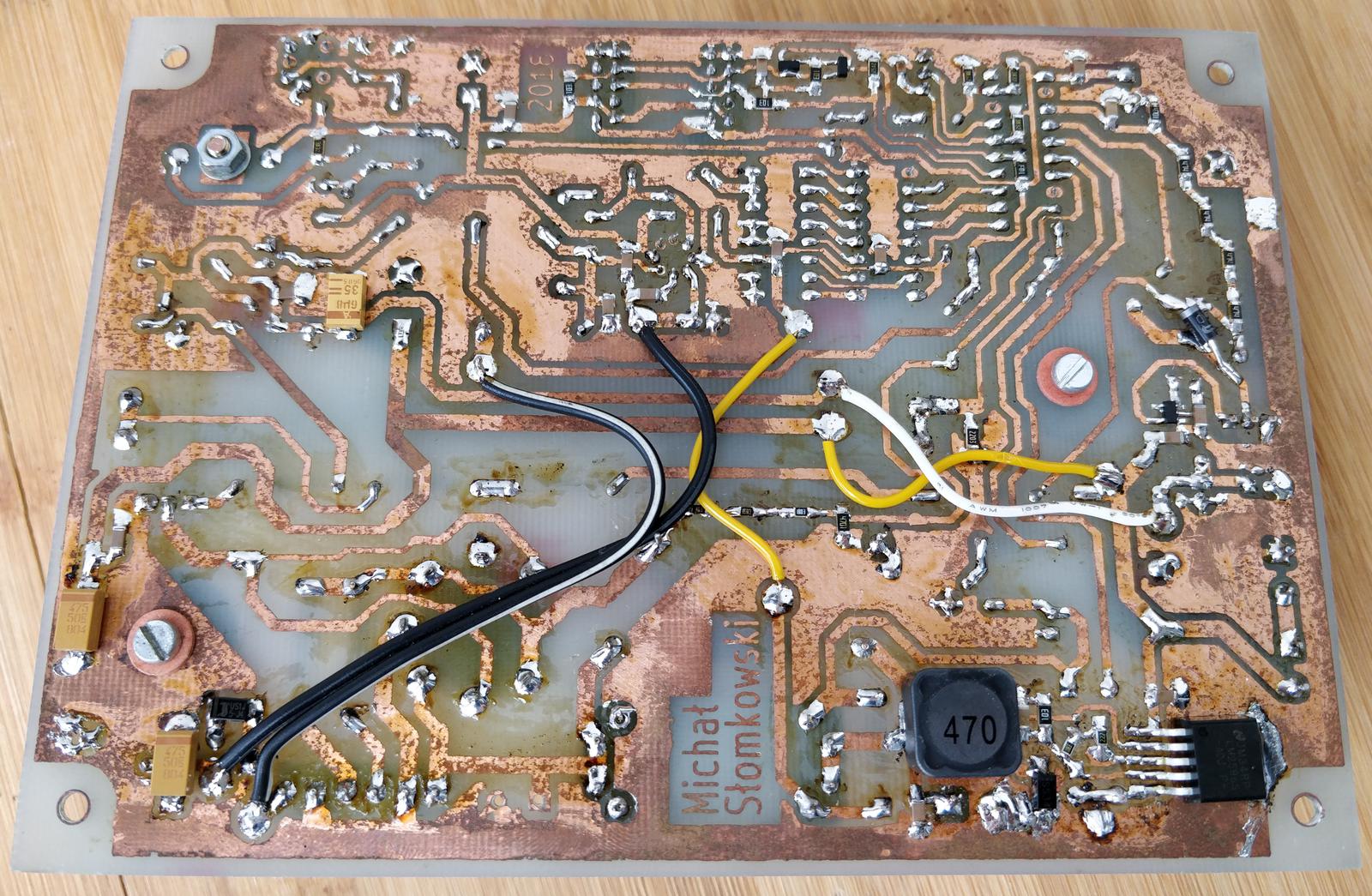
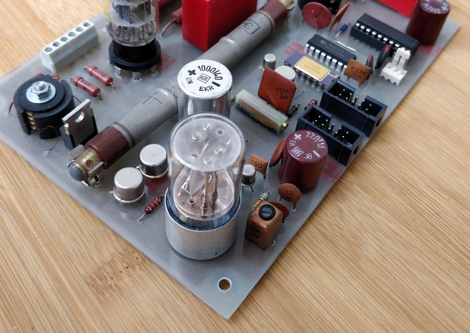
In the original design, there was only one boost converter to supply both 250 and 400 V. This proved to be unmanageable. I split it to two separate converters. I also added dedicated step-down converter to generate 6.3 V for tube heaters. The result is shown in the photos.
The circuit
Since I deliberately used many vintage components the board is surely overengineered. The design could have been changed so several components wouldn’t have been here and the functionality would still have been the same. However I like it the way it is. The schematic is shown below:
The schematic can be divided into following functional blocks:
- crystal oscillator
- system bus connectors and I²C level shifter
- MSP430G2553 microcontroller with shift register and DAC
- 400 V boost converter for Geiger tube and impulse forming circuit
- magic eye boost converter, featuring EAA91 as rectifier, providing 250 V for the eye and -24 V for the grid driver
- magic eye grid driver
- heating voltage step-down converter and relay, germanium transistors

The board is supplied externally with three voltages:
- 3.3 V delivered by system bus, powers the microcontroller
- 5 V from system bus, powers the DAC, grid amplifier, oscillator, I²C level shifter
- 35 V from external connector, powers high voltage converters and heater converter
Several resistors and capacitors have atypical values. This is just because I had them in stock. Almost all of them can be replaced by the nearest one from E6 value series.
Crystal oscillator
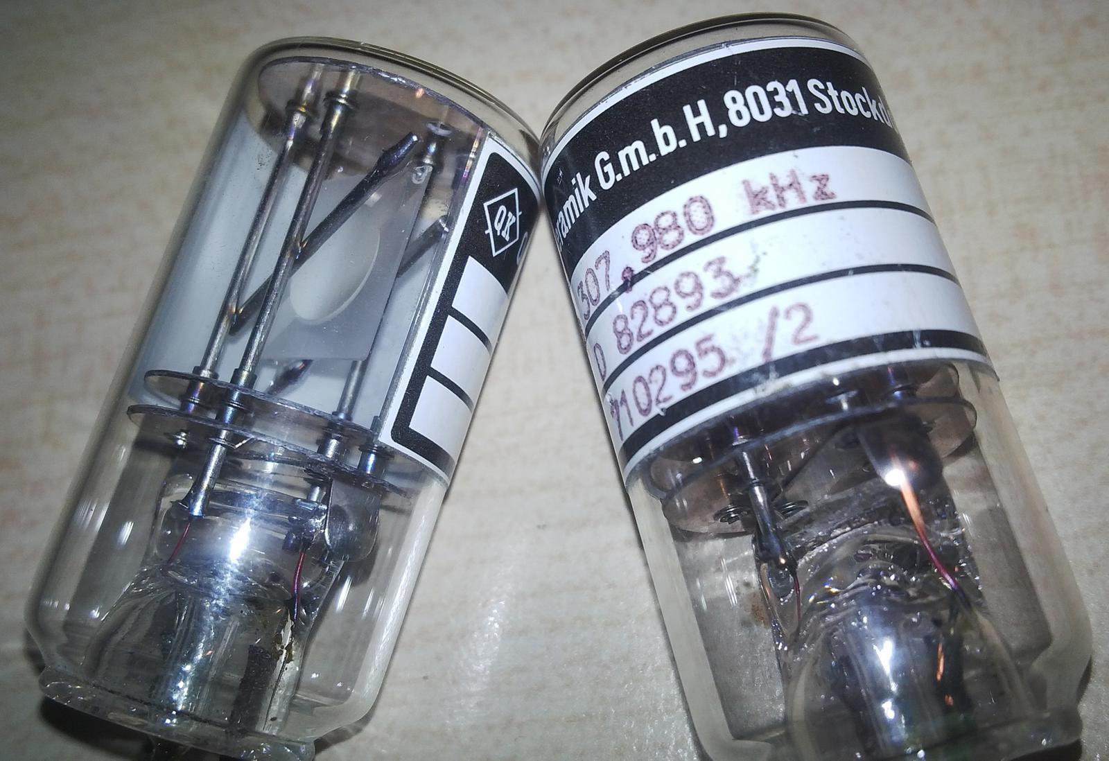
The heart of the oscillator is beautiful quartz in glass envelope.
This crystal was mounted on PCB which I have obtained from some amateur radio enthusiast at local hamfest. The PCB came supposedly from some obscure military equipment. It had a sticker saying 307.980 kHz on it. Believe my surprise when it actually resonated at 5.7 MHz! The design of the oscillator reflects that, because originally I wanted to drive it in overtone mode.
The oscillator is quite sophisticated, it allows overtone mode. The inductor L2 is so called 7x7 radio filter, manufactured by polish Polfer company in the ’80s. The transistor Q7 has metal package. There are four capacitors between the transistor and MCU because the signal crosses some other routes on the PCB, it is better to use caps instead of jumpers in this situation.

Microcontroller MSP430G2553
I own MSP Launchpad for a couple of years but I haven’t done any project featuring MSP430 till now. I utilized microcontroller MSP430G2553 taken directly from MSP430 Launchpad. Reading the datasheet, I felt that the microcontroller seemed quite similar to other 16-bit architectures, it also boasted low power usage. Its internal oscillator supports both high and low frequency modes, you can also feed the chip the external clocking signal, but only low frequency, according to documentation. However, some tinkerers successfully did much higher than that, so do I. To flash the firmware you need two pins: TEST and RESET. I put them on jumper J3 and use Launchpad as programmer.
To control the magic eye tube PWM is the most reasonable, but I had DAC AD558 in beautiful gold-plated ceramic package in stock so I put it on the board. Because spare pins of the microcontroller are precious, I added serial-to-parallel buffer 74HC595 U2. Believe me, I actually had searched for this chip in ceramic package but found none. CE and CS of AD558 are hardwired to the ground so the IC instantly transfers the state of the inputs to the output. 8-bit register latch U2 stores the value loaded by the MCU.
I obtained the DAC AD558 by disassembling some medical device, I don’t remember details.
System bus connectors and I²C level shifter
I²C on the system bus utilises 5 V but MSP430G2553 is powered with 3.3 V therefore the need of level shifting with transistors Q8 and Q9. The bidirectional shifter is only on SDA line, SCL is simple voltage divider. I put two system bus connectors J6, J8 to be able to connect more devices in the future. I used bipolar transistors merely because I had them in stock; the simpler design based on MOSFET-s is used in Orange Pi Zero board.
Geiger tube and 400 V boost converter
Let’s talk about the heart of the device, the STS-5 (СТС-5) Geiger–Müller tube. Drop-in replacement is SBM-20 (СБМ-20). It was a leftover from my earlier project, bloody simple USB Geiger counter, which had been published in Elektronika dla wszystkich, polish hobby electronic journal. The article is available online, polish only. The tube is supplied 400 V from the step-up converter. The microcontroller generates PWM signal at 33 kHz, which drives MOSFET gate driver MCP1402 and subsequently, transistor AOT8N50 (replaceable with any other power MOSFET with suitably high drain-source voltage). The inductor is wound by hand on F1001 core also manufactured by aforementioned Polfer. Diode D3 is fast diode. Zener diode D1 creates 15 V for gate drivers.
I remember that i extracted this cores in my early teens from broken audio amplifier given to me by my friend.
Both cores have AL=2500, Geiger coil has 33 turns. Beat me but I lost info how many turns the eye inductor has. The frequency of the PWM has been tweaked in software for optimal performance. The output voltage is measured by dividing it in divider R9-R14 (because of high voltage, several resistors are used in series) and feed to microcontroller’s ADC to close the feedback loop. In firmware, simple P regulator is implemented - no need for sophistication here.
When gamma particle strikes the tube, it creates ionised trail which shorts the inner electrode with the outer sheath. This generates voltage spike on resistor R20. It is feed directly to the microcontroller’s input, for good measure protected with diode D7.
For filtering capacitor C8 I used MKF 100 nF. 1 μF would be probably better but I hadn’t had the one with vintage look available. From the safety point of view, it is better to avoid using electrolytic capacitors because they hold significant charge and might be dangerous when touched, especially considering the fact that the board is covered by any case.
Tube heater power supply
The device has two vacuum tubes. Naturally they need heating power. They consume 300 mA + 180 mA = ~500 mA at 6.3 V. It is provided by step-down converter based on LMH2596 widely used in cheap Chinese modules. Resistor R8 limits the inrush current when heaters are switched on, it is later shorted by the relay. For the aforementioned reasons, germanium transistor of Russian origin with vintage package drives the relay. The relay is itself reed relay with similar look.
Once I was allowed to take some stuff from liquidated workbench at my hometown’s hospital. There were some interesting medical equipment but also a box with electronic components. I took these transistors because there were looking nice having heavy metal packages.
Magic eye startup sequence begins with the heater converter being switched on. R8 limits the inrush current. After 5 seconds, relay is activated, shorting the resistor. After 15 seconds, when the tubes are reasonably heated, the boost converter is enabled and anode voltage rises.
Jumper JP1 forces the heater voltage on regardless of the signal from the microcontroller. It was used during development to prevent many on-off cycles which is damaging for the tubes.
Magic eye step-up converter
250 V for the anode voltage is provided by the step-up converter built in the same manner as the one for Geiger tube. The difference is an additional winding on the coil which steals some power to generate -20 V for grid amplifier. The storage capacitor is larger, 2.2 μF because of varying load on the converter when stripe has different lengths. The MOSFET gate driver, to make things more complicated, consists of three bipolar transistors (Q2, Q3, Q5) in metal packages instead of dedicated IC. The rectifier is EAA91 double diode tube. According to manual the voltage between cathode and the heater shouldn’t exceed 165 V AC, but it works flawlessly. The tube diode is quite fast and efficient as boost converter rectifier.
During my childhood I used to take pleasure in disassembling electronic devices. Once, the merry old TV-repairman noticed my interest and agreed to bring me some old TV-sets to play with. Subsequently he brought me a couple of old vacuum tube TVs which were no longer working. I spent many days during hot summer vacation in my grandma’s shack playing with screwdriver and taking them apart. I still got the tubes from these among flyback transformers.
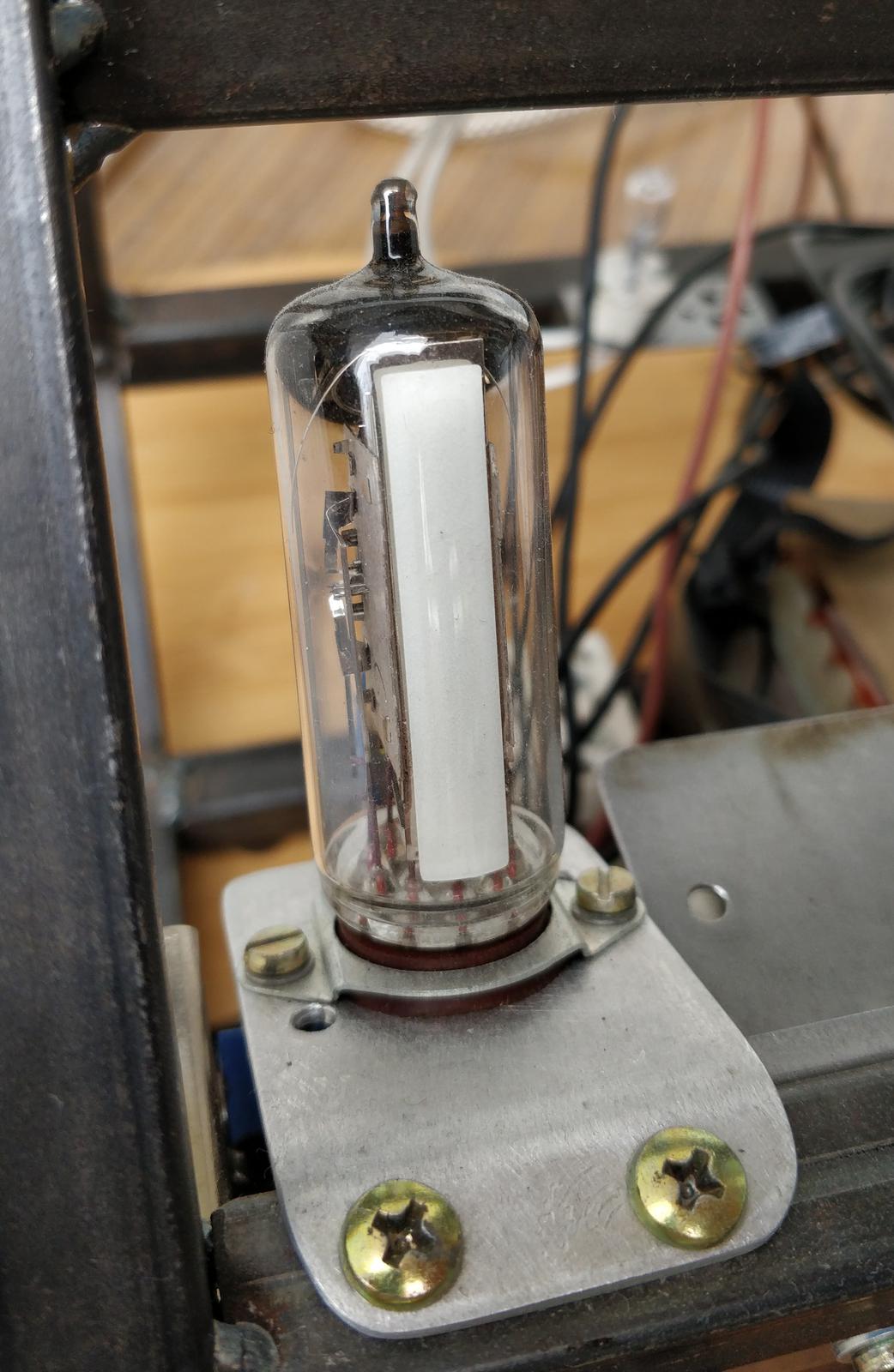
The most prominent feature is the magic tube or tuning indicator itself. The default animation is an oscillation which amplitude depends on the level of radioactivity. Each count generates tick. The source code has separate project written in SDL to emulate the strip on the PC, it was used to make the animation development faster. The real animation is shown in the GIF below.
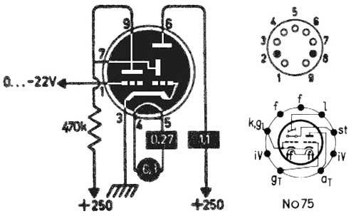
The above is an application schematic of EM84. Other tubes like 6E1P work in the same manner. The external signal drives the triode which subsequently drives the control electrode of the electroluminescent indicator.
R25 is anode resistor, R26 is screen resistor. Putting resistor R26 in series with the screen increases the sensitivity of the device.

Magic eye grid driver
DAC output voltage is within 0 .. 2.55 V range. The grid of EM84 needs voltages from 0 to -20 V. The opamp works in inverting amplifier mode with gain adjustable by RV1. The effective gain should be -20 / 2.55 = ~7.5. Resistor R39 protects the output from accidental shortcuts.
Firmware
Firmware was written in C++ (exceptions and dynamic allocation disabled) and compiled with msp430-gcc. Following the pattern established in main display, the code (root in firmware/geiger) is divided into following modules:
noarch- The application logic. Should be hardware-agnostic and compilable under x86 as well. Covered with unit tests.msp430- Hardware-dependent code, as small codebase as possible.test- unit tests compiled for x86 platform, written with GTest framework.animationtest
with following responsibilities:
- receiving and executing commands from I²C
- driving Geiger boost converter and regulating its voltage with ADC
- driving magic eye boost converter
- counting impulses from the Geiger tube
- animating the magic eye
- controlling the 6.3 V heater converter and relay
Everything is done in main loop. The loop contains timer which is executed 100 times per second. Within it, the boost converted P regulator is called to measure the ADC voltage and set PWM’s appropriately. Also, the animation is run. The I²C requests are not executed from the loop, but asynchronously from the interrupts. The requests are as follows:
Get device state
To trigger read, send 1 to the device, then read response:
geiger voltage|geiger PWM|magic eye state|eye animation mode|eye voltage|eye PWM
| Value | Size | Description |
|---|---|---|
| geiger voltage | 2 | raw voltage of Geiger supply voltage read from ADC, need to be converted to volts |
| geiger PWM | 1 | current PWM value for Geiger boost converter |
| magic eye state | 1 | |
| eye animation mode | 1 | |
| eye voltage | 2 | raw voltage for magic eye |
| eye PWM | 1 | current PWM value fo magic eye boost converter |
Magic eye is not enabled at power up. You can enable or disable it by sending 5 request. Because this is a vacuum tube, which needs heating, I devised 4 states:
DISABLED- self explanatory (0)HEATING_LIMITED- heater voltage converter enabled, the heaters are supplied through resistor to limit inrush current (1)HEATING_FULL- the resistor is shorted by the relay, the full voltage applied to the heaters (2)RUNNING- boost converter started, the anode voltage applied to the tubes (3)
The animation itself can be automatic (ANIMATION - 0) or manual (FIXED_VALUE - 1). In manual mode the DAC output value is set by separate request.
Get Geiger counter state
The device counts ticks from the tube in cycles. For the measurement of ambient radiation to be accurate, the interval has to be quite large, I use 5 minutes (300 seconds). It is possible to change this interval, but this feature is now unused.
Send 2, then read response:
flags|counts in current cycle|counts in previous cycle|cycle progress|cycle length
| Value | Size | Description |
|---|---|---|
| flags | 1 | bit 0 - new cycle has just started. Cleared after read. Bit 1 - at least one cycle has completed. |
| counts in current cycle | 2 | |
| counts in previous cycle | 2 | |
| cycle progress | 2 | in seconds |
| cycle length | 2 | in seconds, 300 by default |
Set Geiger counter configuration
'3'|cycle length
| Value | Size | Description |
|---|---|---|
| cycle length | 2 | in seconds |
Each execution of this request also resets all counters.
Reset Geiger counter
'4'
Resets all counters.
Set magic eye configuration
'5'|enabled|animation mode
| Value | Size | Description |
|---|---|---|
5 |
1 | Magic byte |
| enabled | 1 | 0 or 1 |
| animation mode | 1 | described above |
Set magic eye DAC value
Available only in FIXED_VALUE mode.
'6'|value
| Value | Size | Description |
|---|---|---|
6 |
1 | Magic byte |
| value | 1 | From 0 - bars far apart to 255 - bars touching each other. |
Set display brightness
Changing brightness modifies the output voltage of the boost converter. Voltages for each brightness level:
0- 0 V1- 100 V2- 140 V3- 180 V4- 210 V5- 250 V
Changing anode voltage has an effect on the base position of the bars on the eye, but this change is acceptable.
'7'|brightness
| Value | Size | Description |
|---|---|---|
7 |
1 | Magic byte |
| brightness | 1 | From 0 (boost converter shut down) to 5 (max). |
Strange problems with I²C and boost converter transients and spikes
During the development I encountered strange problems with I²C communication. Issuing write commands worked well, but reading data from the MCU always resulted in some garbage or 0xff. Investigating the problem I determined that I²C code works correctly only when DCO clock frequency is 16 MHz. 12 MHz worked too, but no so reliably. Unfortunately when the MCU frequency was so high, it was prone to accidental resets caused by voltage spikes generated by boost converter. I devised hackish solution: CPU works normally on 8 MHz, switches to 16 MHz when doing I²C slave read, then switches back. External quartz oscillator still drives the internal timers and other peripherals. It is very dirty, but works. If you have any idea, what is going on, don’t hesitate to contact me!
Animation visualizer
animationtest is simple application written in SDL to visualize the magic eye animation on the PC. It imports the appropriate code from noarch and runs it with following effect:
Pressing space emulates a gamma count. The idea of the animation is constant movement of the bars. The arrival of gamma particle causes the bars to touch. The average position of the bars depends on the average radiation. The higher it is, the closer they are.