USB Geiger counter
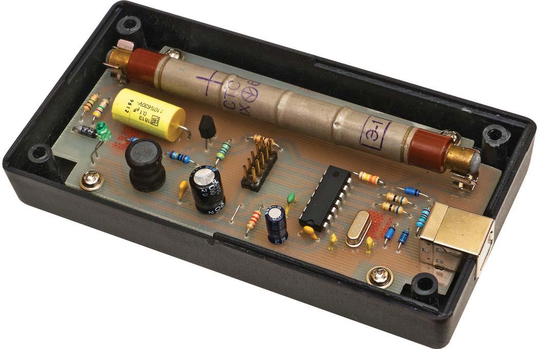
This project was featured in Elektronika dla wszystkich 10/2013, a Polish hobby electronics journal. The original PDF in Polish is available for download. I translated it to English, edited it a bit and republished it here.
Introduction
Some time ago I came across a Soviet STS-5 (СТС-5) Geiger–Müller tube. It is an equivalent of the fairly popular SBM-20 (СБМ-20), used, among other things, in the Polish radiation survey meter DP-75. I decided to make use of it by building a computer Geiger counter. After searching the Internet, I found out that I was not the first to come up with this idea. Although many circuits with similar or even identical capabilities had been published, I managed to build a counter that stands out for its exceptional simplicity, making it friendly for beginner electronics enthusiasts as well as IT people, for whom this circuit can be an interesting addition to their homelab. The project repository, with all source code and PCB layouts, is published on GitHub.
I would rate the difficulty of the project at three stars. The electronic circuit itself and its assembly are straightforward and would get two; the third comes from the presence of high voltages and the use of a rarely encountered component. An additional complication may be the installation of monitoring software on the computer, as it lacks a graphical user interface.
What does it do?
The device measures background radiation round the clock and saves the results to a text file, a MySQL database, or the cosm.com service providing
data collection and graph generation (cosm.com has since been shut down).
Because I intended to use it primarily in a server environment, the focus was on adapting the program to Linux; running it under Windows is, however, entirely possible. With no GUI, some IT knowledge is required to configure the device properly. Due to the lack of a display, operation without a computer is also not possible.
The device, in addition to its educational value, can serve as a crude warning system for elevated radiation in the user’s area, not only during an unlikely nuclear disaster but also in everyday life. There are a lot of buildings built of stone containing a high concentration of uranium ore. In some basements, the radioactive noble gas radon accumulates. Sometimes the radiation intensity from these sources can exceed the permissible level. Being aware of the hazard, one can limit the time spent in such rooms, for example by refraining from sleeping in them.
Types of ionizing radiation
Radioactivity surrounds us throughout our lives. The soil itself emits radiation, buildings do too (ash from coal power plants, which contains uranium, was commonly used as a concrete additive), as does the air (due to volcanic eruptions and the presence of radon), and even bananas! Ionizing radiation also reaches us from space. The impact of human activity (power plant fires, nuclear tests) is negligible on a global scale. However, it gains significant importance near the site of the accident or test and wherever the radioactive cloud reaches, persisting for up to several tens of days after the disaster.
There are four types of ionizing radiation: alpha, beta, gamma and neutron. Alpha particles are helium nuclei carrying a positive charge. They are not very penetrating; a regular sheet of paper stops them completely. Beta radiation consists of electrons. Aluminum foil stops them. The really penetrating one is gamma radiation. Unlike the previously mentioned types, it is electromagnetic. Several centimeters of lead are required to attenuate it sufficiently. Due to the low penetrating power of alpha and beta particles, common counters (including the one described here) are sensitive mostly to gamma and hard beta radiation. An alpha particle detector has a special construction (a thin mica window), which significantly raises the cost. The first three types of radiation can be generated by nuclear decay processes, so they are often grouped together. Neutron radiation is different: although some neutrons reach us from space, significant amounts of them can only be generated by fission or very specialized devices.
As research on radioactivity and its effects on living organisms progressed, many units of measurement were devised, such as roentgens, sieverts, grays, rads and rems. We are mainly interested in the unit of equivalent dose, which reflects the biological effect of the radiation a human receives. Radiation intensity is given as the dose divided by the exposure time. The current standard unit is sievert per hour (Sv/h). This unit is very large; background radiation is usually measured in microsieverts per hour. In my place of residence, the value ranges between 0.1 and 0.2 µSv/h.
The detector tube
Before describing the construction of the device, it is useful to discuss the working principle of its heart, the STS-5 radiation detector tube. Unlike the popular Polish BOB-series Geiger tubes, it has a sensitivity range reaching down to background radiation. The counter takes the form of a metal tube (the negative electrode) filled with a noble gas and a small amount of halogen at reduced pressure. Through its center runs the positive electrode, a thin wire. When a particle or a gamma photon passes through the gas volume, it ionizes some atoms of the gas inside the tube. The electrons, now free from the atoms, are quickly accelerated in the strong electric field between the electrodes. Moving at high speed, they collide with other atoms, ionizing them as well. An avalanche discharge occurs, rapidly encompassing the entire gas volume between the electrodes.
Seen from outside, each quantum of radiation arriving at the tube results in a brief current pulse flowing through the counter. Theoretically, the current can reach large values, but in practical circuits it is limited by the value of the anode resistor. During the avalanche discharge the counter is insensitive to new particles. This period is called the dead time of the counter and sets the upper limit of its measuring range. For popular tubes this limit is on the order of hundreds of pulses per second; at background levels of a fraction of a count per second, this doesn’t matter.
For the avalanche discharge to occur, the detector must be biased with a high voltage, on the order of several hundred volts. On the count rate vs. voltage curve, three main regions can be distinguished: rise, plateau, and continuous discharge. Below the starting voltage the tube does not count at all. Above it, the count rate rises steeply until it reaches the plateau. In the continuous discharge region, the electric field intensity is high enough that the avalanche discharge does not quench after the radiation strike, or false counts are generated. The detector normally operates in the plateau region, where the count rate depends least on the voltage. For the STS-5 used here, the plateau is 80 V wide and its center falls at 400 V.
Another important parameter of the tube, besides the supply voltage characteristics, is the sensitivity, that is, the count rate per unit of radiation. The STS-5 datasheet (quite old) states it as the number of pulses per second per 1 mR/h. For amateur use it can be assumed that 1 R is approximately 10 mSv, so 27 counts per second corresponds to 10 µSv/h.
Circuit description
With the tube covered, we can move on to a discussion of the rest of the circuit. Tasks such as generating the waveform for the converter powering the detector, counting pulses, and USB communication are handled by the ATtiny24A microcontroller, chosen for its low price and sufficient number of pins. After many tweaks and optimizations, the full functionality was fitted into 2 kB of program memory.
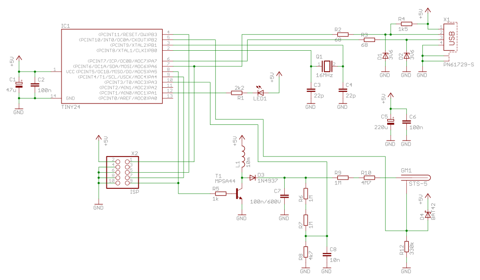
The high voltage required for detector operation is generated by a simple step-up converter. The only
inductive element is a standard 10 mH choke L1; this solution relieves the builder of hand-winding coils or transformers. The waveform
frequency was set to 4 kHz with a variable duty cycle. A low-power MPSA44 bipolar transistor, interchangeable with the BF487, is used as the switching element. Its maximum collector-emitter voltage is 400 V; the default operating voltage was therefore set to
395 V. The induced voltage pulses charge capacitor C7 through diode D3. Ideally this would be an ultrafast
diode; accepting somewhat lower efficiency, the inexpensive and common fast-recovery 1N4937 was used. Resistors R6,
R7, R8 form a voltage divider used for measurement by the analogue-to-digital converter built into the microcontroller. The
microcontroller firmware implements a simple P controller that stabilizes the voltage at the designated level.
The pulses of current from the Geiger tube generate a voltage across resistor R12 and are directed straight to the microcontroller’s input.
No other pulse-shaping circuit was used. Thanks to the high input impedance, the circuit has sufficient sensitivity. For additional protection, a Schottky
diode D4 (BAT42) is used, limiting the pulse amplitude to a level slightly above the supply voltage. In the
firmware, a logic-level change at the input triggers the PCINT1 interrupt, which increments a counter on every other edge, i.e. once per
pulse.
The circuit communicates with the PC via the USB interface. To make the hardware as simple as possible, I decided not to use a USB-to-RS232 converter (such as those from the FTDI family), but to implement USB support directly in the AVR, using the free V-USB library from obdev.at, which implements the USB 1.1 standard purely in software. The bus itself has a very complex architecture, and the library authors deserve respect for creating the library and making it available under the GNU GPL license.
The USB bus has a tree topology. All devices are connected to the host through special devices called USB hubs. At the very top sits the root hub. Up to 127 devices can be connected. Data transfer speeds are 1.5, 12 and 480 Mbit/s, and up to 5 Gbit/s for the 3.0 standard. Devices have one or more so-called endpoints. Between the endpoint of a device and the host, a virtual communication channel can be established through which data flows to and from the device.
To cover different needs, the standard defines four types of connections (transfers) between endpoints: control, interrupt, bulk, and isochronous. Every device must provide at least one control endpoint. This transfer mode is distinguished by a small amount of data per frame and error checking. As the name suggests, it is used to control device operation and determine its configuration. For simplicity, the Geiger counter presented here uses only this channel.
Interrupt transfer mode has characteristics similar to control transfer. It is used to send small amounts of data within a guaranteed time. A classic application is a computer mouse, where transmitting the current position is particularly important for the user’s comfort (especially in games).
Bulk and isochronous transfers are used for transmitting large amounts of data. Isochronous transfer additionally enforces immediate delivery at the cost of retransmission. Incorrectly delivered data is lost irrecoverably. This is important for audio or video applications. A single bit error is usually inaudible, whereas the need to re-transfer a data packet would cause a momentary gap in audio playback. For bulk transfer, correctness is the priority. It is used by all mass storage devices: pen drives, hard drives, etc.
To group similar devices from many manufacturers into one category, USB classes were defined. There are many of them, e.g. printer, mass storage and hub. The Geiger counter presented here is recognized by the host as a Human Interface Device, that is, a device for user input. This class normally includes mice, keyboards, and joysticks. I chose this class because Windows pops up a message whenever a device without a driver is connected, and HID devices don’t need one.
In addition to the class, each device has a pair of numbers: the manufacturer identifier (Vendor ID) and the product identifier
(Product ID). The manufacturer code is assigned by USB-IF, the organization that
created the standard. Unfortunately, the cost of certification and of obtaining a number, amounting to several thousand dollars, is beyond the reach of
amateur electronics enthusiasts. Fortunately, there are vendor and product ID pairs available for free use, provided by Obdev. One of them is
16c0:05df with the HID class assigned. However, if many projects use the same pairs, the problem of telling them apart arises. They can be
distinguished by reading the so-called string descriptor. The manufacturer’s name, device name, and many other parameters are stored there
as human-readable strings. They are available under the Manufacturer and Product identifiers. The license under which Obdev makes
the IDs available requires the designer to use, in the Manufacturer string, the name of an internet domain they control or their e-mail
address. The Geiger counter described here therefore has the manufacturer slomkowski.eu and the product name USB Geiger. These
strings (case-sensitive) are used to identify the device.
A USB cable has four wires: ground, the +5 V 500 mA supply, and the signal lines D+ and D−. The signal lines operate
differentially at logic levels of 0 V and 3.3 V. Resistors R2–R4 together with diodes D1 and D2
implement a voltage level converter between the USB bus and the microcontroller, as recommended by the V-USB library authors. It limits the voltage coming
out of the microcontroller to 3.3 V. The Zener diodes have a nominal voltage of 3.6 V because this voltage is specified at a relatively high current
(typically 10 mA). At lower currents the stabilization voltage is correspondingly lower, which for 3.3 V diodes could cause unstable bus operation.
Although the microcontroller has an internal oscillator, an external crystal resonator is required in order to meet the strict timing requirements of the USB bus. The library supports several frequency values, each requiring a different version of the code. A 16 MHz crystal was used together with load capacitors of the usual values.
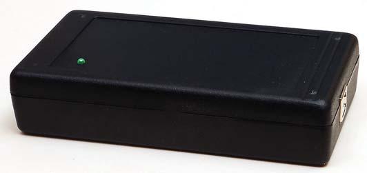
The LED remains lit when the device is connected to the computer, and briefly goes out on each detected particle. An ISP socket with the STK200 pinout is also placed on the board to facilitate any firmware updates. With a detector supply voltage of 395 V, the circuit draws less than 45 mA from the USB port (approximately 230 mW).
Tips for assembly
Warning
Working with high voltage can be lethal—disconnect power before starting and verify all wiring is correct and properly isolated before powering up.
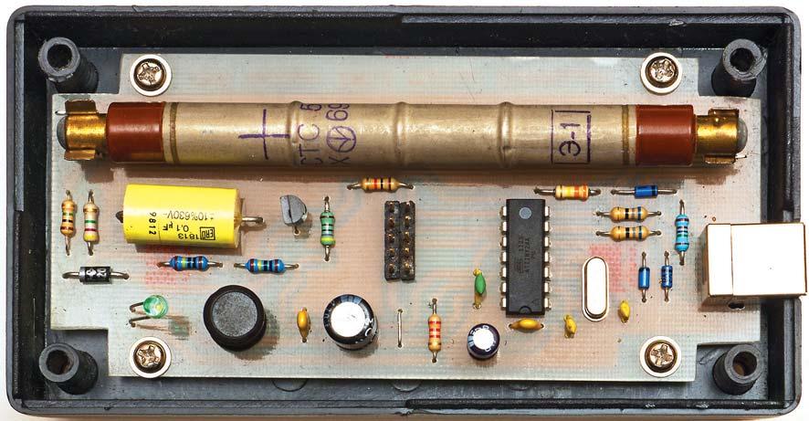
To make assembly easier for beginner electronics enthusiasts, only through-hole components were used. The assembly is straightforward except for the detector itself. Tin-plated PCB fuse holder clips were used to mount it.
The values of all components except the crystal resonator do not have to be adhered to strictly, but remember that in some cases the program settings
must be changed accordingly. The resistors forming the voltage divider R6–R8 should have a manufacturing tolerance of 1% so that
measurement results are meaningful. This is especially important since transistor T1 operates close to its maximum collector-emitter
voltage.
The board was designed to fit in the Z-34 enclosure. When making the board yourself, remember to cut the corners to fit the enclosure. Adapting the enclosure involves cutting a rectangular opening for the USB socket and a hole for the LED.
The circuit requires no initial calibration; once connected to the computer it should be visible in the system and the LED should light up, flashing
from time to time. Despite that, it is sensible to measure the voltage generated by the converter. Due to its low current capacity, it cannot be measured
directly across capacitor C7, as connecting a meter will cause an immediate voltage drop. It must be measured at the divider output and
recalculated accordingly.
When working on the circuit while connected to the power supply, caution must be exercised due to the high voltage of 400 V. Although the charge stored in the 100 nF capacitor is not life-threatening, it can cause an unpleasant shock or a local burn.
The source code and the compiled HEX file for the microcontroller are available in the GitHub repository. You do not need a Git client to download it. There is a button on the page for downloading everything as a ZIP archive.
Software on the computer
The software on the PC is an essential part of the system, which is why it has been given its own section. It was written in Python 2.7, mainly
due to its portability and ease of learning for beginners. It consists of a core that retrieves data from the device and several modules that subsequently
send it to various places, such as a MySQL database, the cosm.com service, or a text file. Creating a custom module or modifying an existing one
is very straightforward, and an advanced user should have no trouble with it. All settings are stored in the configuration.ini file. As the
program is intended to run in the background, a graphical user interface was omitted.
Since radioactive decay is a random process, counts are summed over a measurement period, one minute by default; longer periods give better accuracy. My counter runs on a Raspberry Pi, an increasingly popular microcomputer with an ARM processor and Linux on board. Running the program under Windows should not pose any difficulties.
What can be changed?
The most obvious change from the original design is the use of a different radiation detector tube. Due to the large variety of dimensions of common
Geiger tubes, it was not possible to create a board suited to all of them. The SBM-20 tube can be used without any changes. Others may require connecting
the terminals with wires. The supply voltage can be easily changed in the microcontroller’s source code as well as in the computer program configuration.
Keep in mind that using voltages higher than 400 V requires replacing transistor T1 with a type having a correspondingly higher permissible
operating voltage. The nominal sensitivity can be easily changed in the host software configuration file.
The microcontroller’s firmware uses virtually all the available Flash memory; adding even a single new instruction is highly problematic. Fortunately, the ATtiny24 can be replaced with an ATtiny44, which has 4 kB of Flash memory.
The host software is the easiest part to extend. Thanks to the use of Python, it is straightforward to implement new features such as sending data to other services, generating detailed statistics, or sending SMS or e-mail alerts about hazards. Advanced readers can fork the project’s GitHub repository and report any bugs found.
Bill of materials
| Type: | Component: | Value: | Notes: |
|---|---|---|---|
| Capacitor | C1 |
47 µF | electrolytic |
C2, C6 |
100 nF | ceramic | |
C3, C4 |
22 pF | ceramic | |
C8 |
10 nF | ceramic | |
C5 |
220 µF | electrolytic | |
C7 |
100 nF / 600 V | MKT | |
| Resistor | R1 |
2.2 kΩ | |
R2, R3 |
68 Ω | ||
R4 |
1.5 kΩ | ||
R5 |
1 kΩ | ||
R6, R7 |
1 MΩ | tolerance 1% | |
R8 |
4.7 kΩ | tolerance 1% | |
R9 |
1 MΩ | ||
R10 |
4.7 MΩ | ||
R12 |
330 kΩ | ||
| Semiconductor | D1, D2 |
Zener 3.6 V | low power |
D3 |
1N4937 | ||
D4 |
BAT42 | ||
T1 |
MPSA44 | ||
IC1 |
ATtiny24 | DIP | |
LED1 |
3 mm LED | ||
| Other | GM1 |
see article | Geiger tube |
L1 |
10 mH | choke | |
Q1 |
16 MHz | quartz resonator | |
| USB socket | PCB mount | ||
| Goldpin 2 × 5 |