QO-100: Modding satellite LNBs for external 25 MHz clock
Currently, I’m in the process of setting up my ham radio station for the QO-100 satellite. Receiving its narrowband transponder is a piece of cake: a >= 60 cm dish antenna with an attached Ku band low-noise block downconverter and any SDR capable of receiving ~740 MHz (even an RTL-SDR) are all one needs.
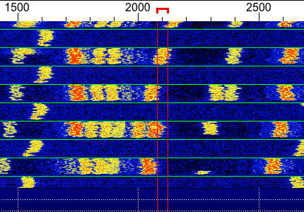
The major problem with reception is the frequency stability of the LNB’s local oscillator. The lower end of the QO-100 narrowband downlink, 10 489.500 MHz, is downconverted within the LNB to 739.500 MHz. The LO frequency of 9750 MHz is achieved by multiplying a 25 MHz crystal frequency by 390 using a PLL. Because of the large multiplication factor, every 1 Hz change in the crystal frequency shifts the output by 390 Hz, which is 9.75 kHz per ppm. An uncompensated crystal drifts by a few to several tens of ppm over temperature, which moves the signal far beyond the SSB passband or an FT8 decode window. Even minuscule drift is visible on the WSJT-X waterfall:
For QO-100 specifically, some SDR software, such as SDR Console or SDRoxide, can minimize this drift by locking to the middle PSK beacon. However, beacon locking only corrects the received signal; it does nothing for the uplink transmitter, which drifts on its own. It also ties me to software that supports this feature and would limit my options if I wanted to do something else, such as terrestrial 10 GHz QSOs or 10 GHz EME.
Therefore, I decided the better and more tinkery approach would be to inject a stable 25 MHz reference from within the shack. Nothing unusual: the same modification has already been documented for the Maclean MCTV 670, the Bullseye, and other LNBs. This 25 MHz signal can be provided by a stable TCXO, OCXO, or even a GPS-disciplined oscillator for the greatest long-term stability. In this article, I describe the modification for the Inverto-branded twin LNB I had at hand. If I modify another brand of LNB, I’ll update this article.
Inverto IDLH-TWL410-HMPRO-OPN low-noise block
The 80 cm dish accompanied by this twin LNB came with my house, installed by the previous owner. It hung there dormant for the greater part of a decade. Nevertheless, it turned out to be in good condition and easy to modify.
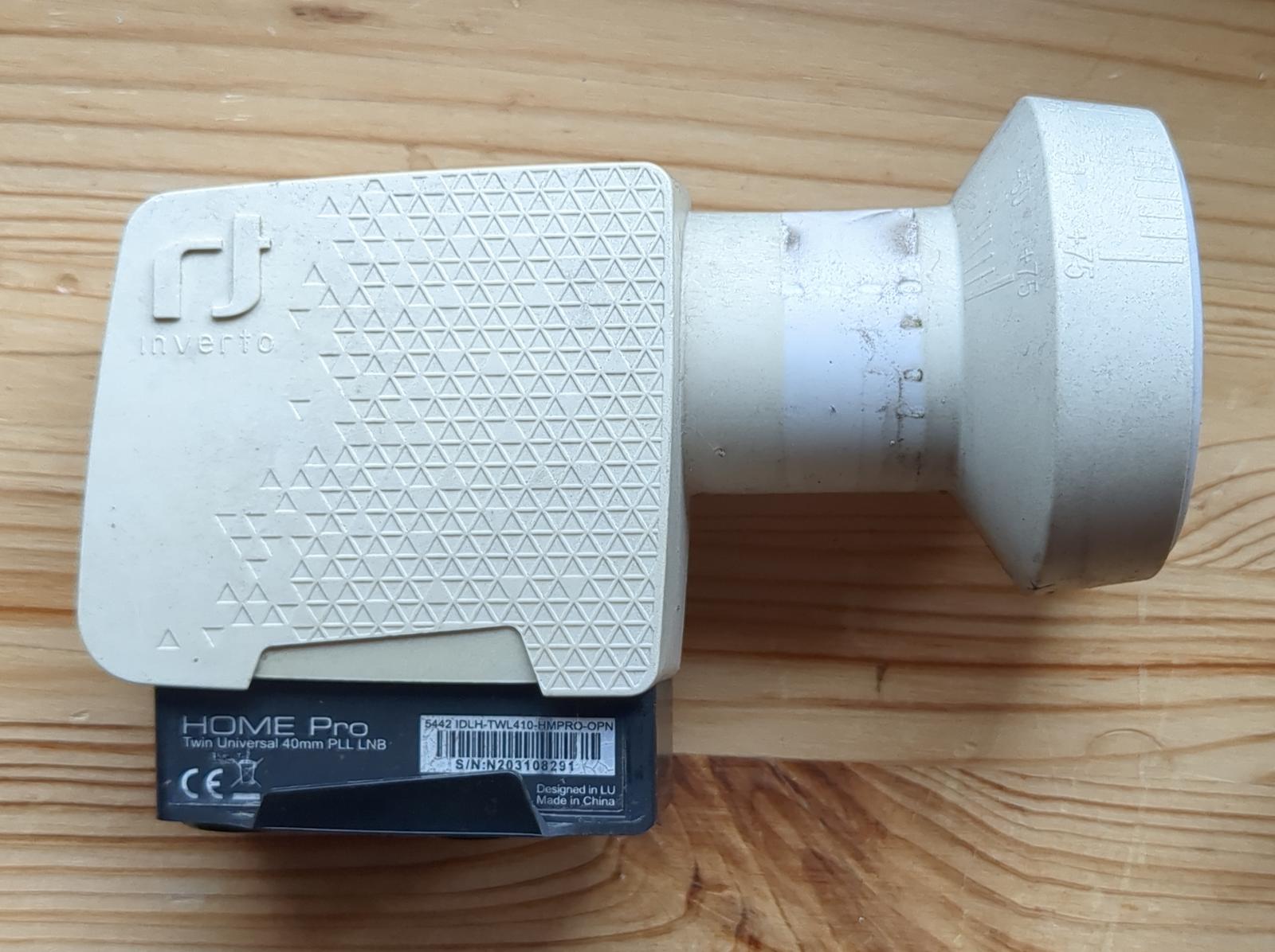
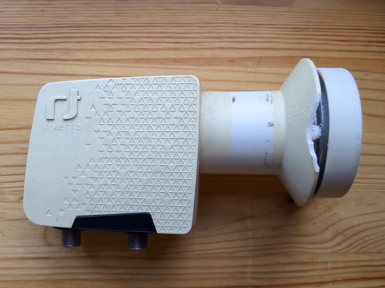
The device was manufactured in 2009 but is still available online for around 13 euros. The product website and the manual are available too. For reference, the full label reads:
Inverto Home Pro
Twin Universal 40mm PLL LNB
5442 IDLH-TWL410-HMPRO-OPN
The LNB is built around a Rafael Micro RT320N chip, a popular specialized IC for dual-output LNBs, found in many brands including Opticum and Bullseye. The satellite broadcasting lower band is specified as 10.70–11.70 GHz, so QO-100 at 10.49 GHz is formally out of band. In practice, the input filter rolls off gently enough and the reception is still perfectly OK. The current draw is about 120 mA. The polarization, as with any other LNB, is set by the supply voltage; the switching point is at 14.3 V. Since the internal voltage is regulated by two 78M06 regulators (one for each output), vertical polarization (the low-voltage mode, suitable for the narrowband transponder) can be maintained with a supply as low as 9 V.
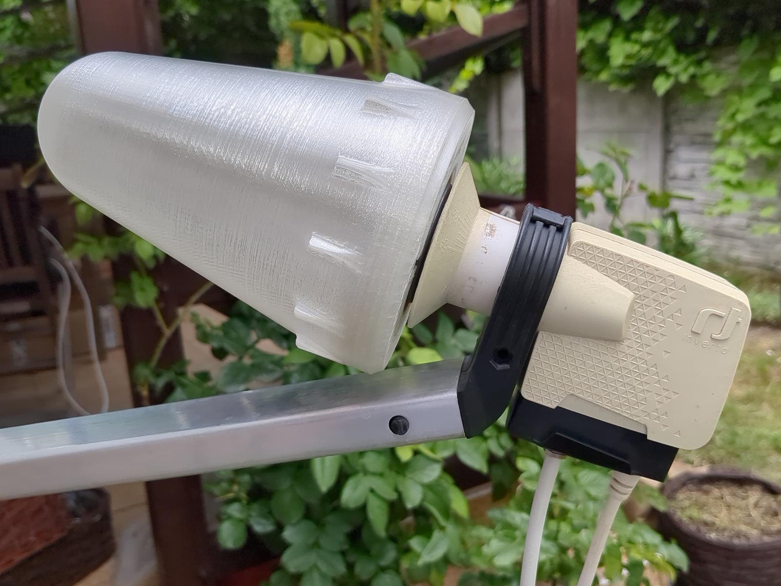
The horn’s outer diameter is 60.7 mm. By the way, for the QO-100’s uplink, DC8PAT provides a 3D-printable helix antenna design for the 60 mm horn.
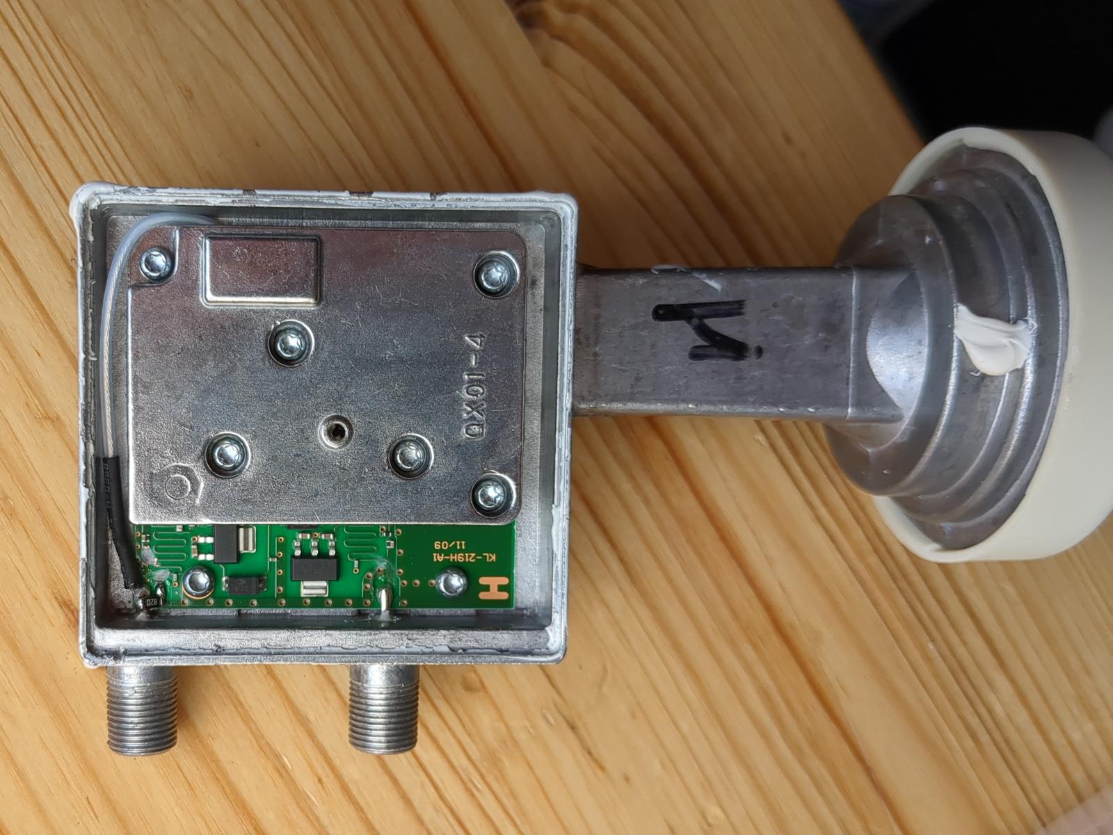
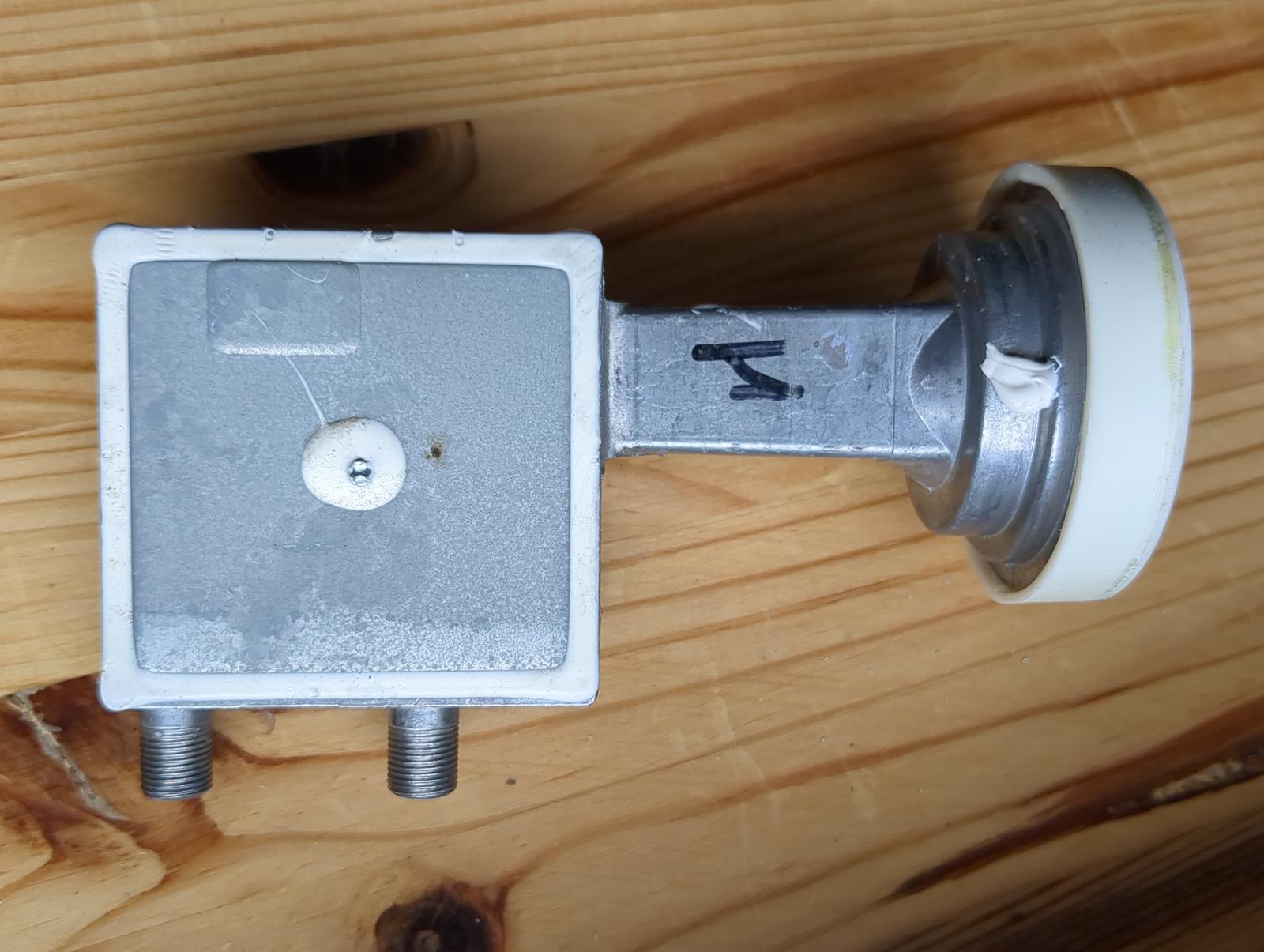
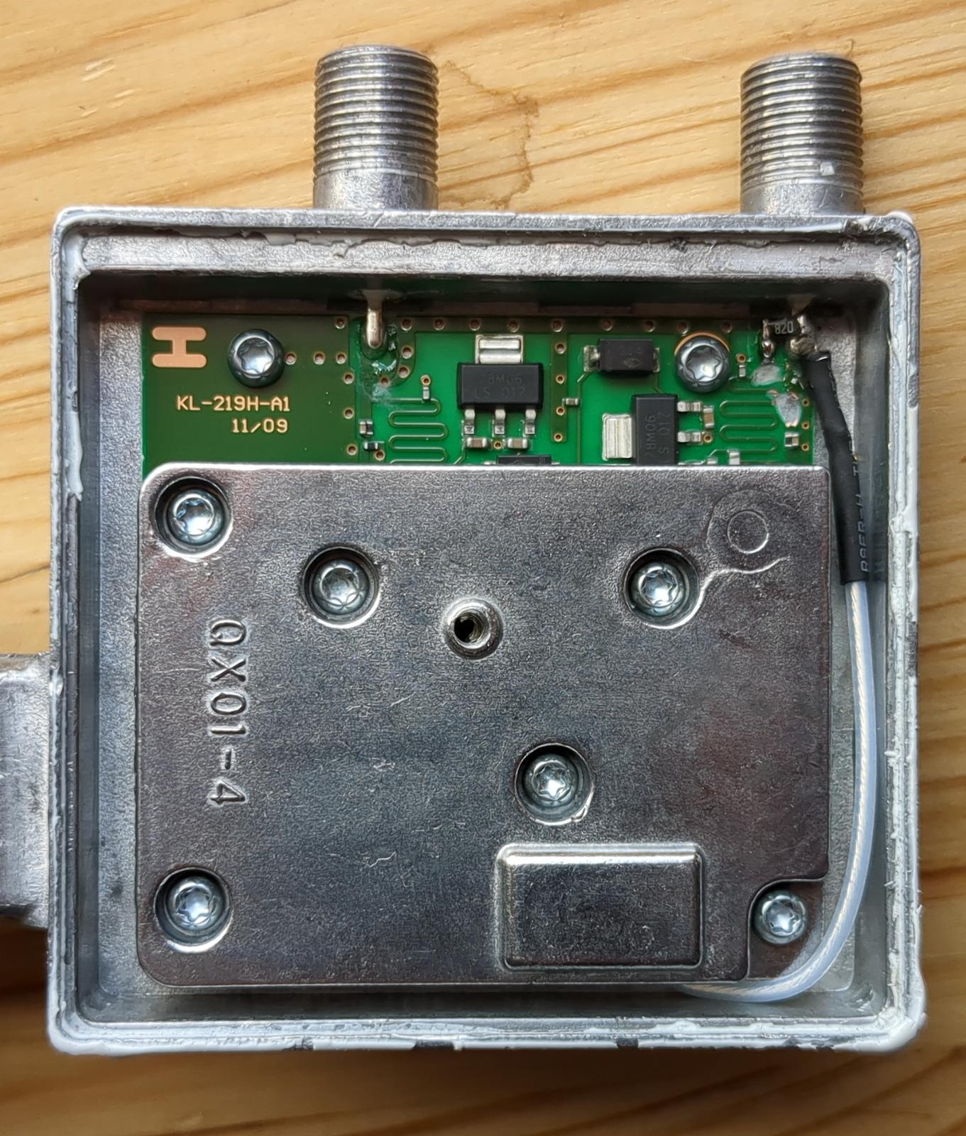
To gain access to the electronics, the silicone seal must be cut away with a sharp knife first. Then the housing is opened, and the inner shield is unscrewed with a Torx T8 screwdriver, revealing the PCB filled with RF components. Fortunately, access to the crystal resonator is straightforward without removing the board.
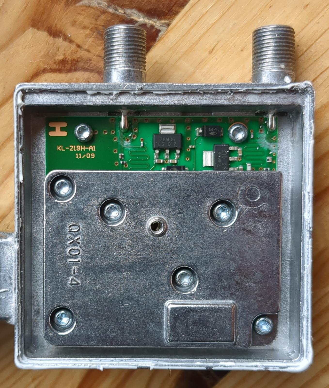
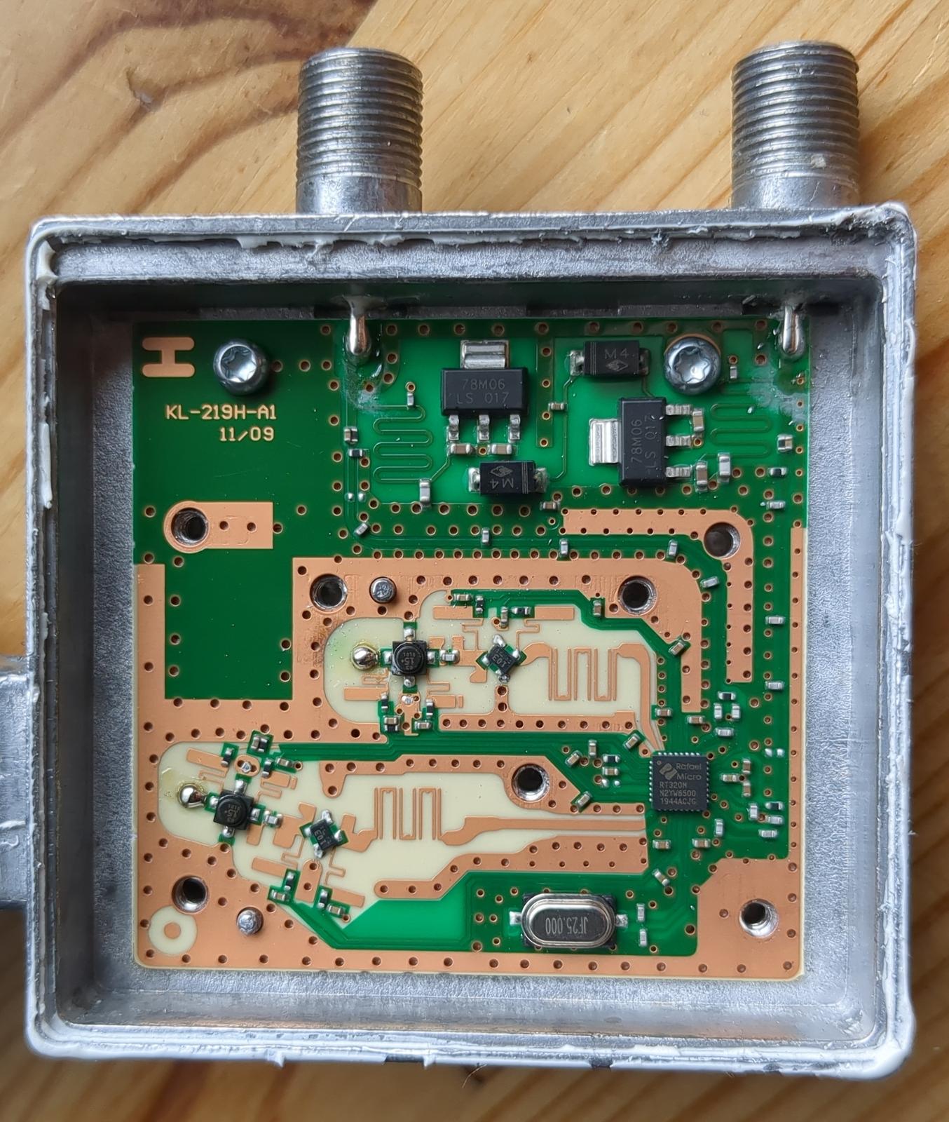
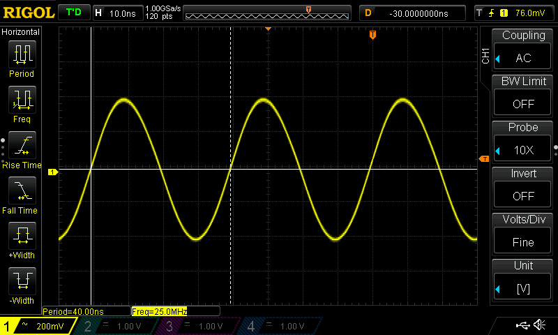
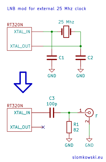
I checked the waveforms on the crystal pins with an oscilloscope. The crystal and two capacitors form a standard Pierce oscillator, the same topology
found in most microcontrollers. At the oscillator’s XTAL_IN pin there was a clean 25 MHz sine wave with 800 mV p-p, and this is where the
external reference has to be injected.
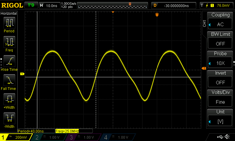
XTAL_OUT shows a distorted sine wave at ~700 mV p-p. This is the output of the internal inverter, and the distorted shape is normal for a
Pierce oscillator. This pin is left unconnected after the modification.
Modification
To deliver the external reference from the shack over standard 75 Ω coax, one of the two F outputs is repurposed as the clock input. I chose the one further from the horn, as it gives a shorter wire run inside the LNB to the crystal pads. The reference level should match the original crystal signal, about 800 mV p-p, which is roughly 0 dBm into the 82 Ω termination. Note that this value was measured with the oscilloscope probe loading the oscillator, so treat it as a ballpark figure. A sine wave output is preferable: the harmonics of a square wave leak into the LNB circuitry and can produce spurious signals in the IF. If only a square wave source is available, its harmonics should be filtered out with a low-pass or band-pass filter, preferably a crystal ladder filter made of two or three crystals. Keep in mind that a crystal filter passes only a narrow band around its nominal frequency.
The clock circuit inside the LNB is shown in the schematic below. An 82 Ω resistor provides an acceptable termination for the 75 Ω coax, and a 100 pF capacitor blocks DC.
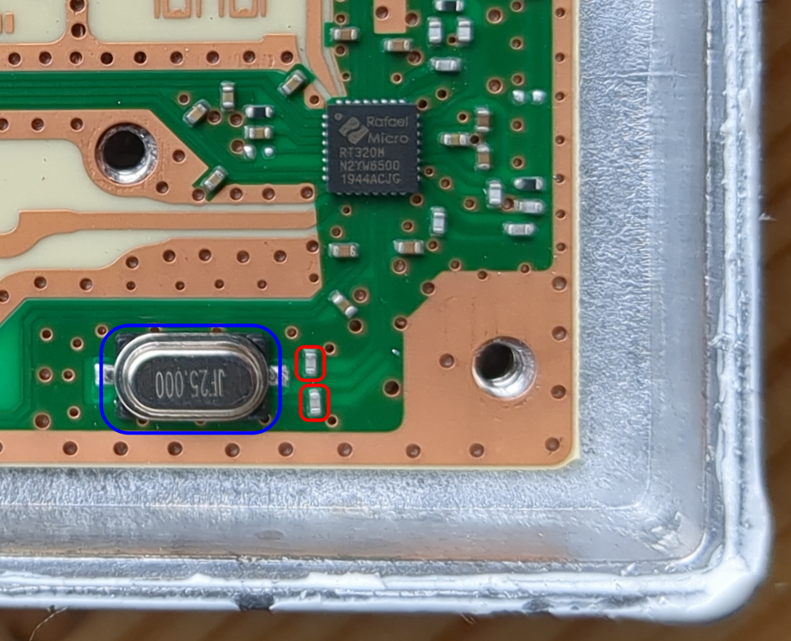
To begin the modification, unsolder the crystal resonator marked blue. You can use a hot air station or two soldering irons to
heat both pads simultaneously. Then, unsolder the two very small capacitors marked red (the crystal load capacitors). The one on
XTAL_IN must be removed, as together with the 100 pF coupling capacitor it would form a divider attenuating the injected reference. The one on
XTAL_OUT is no longer needed either. I covered each with a large blob of solder to heat both pads at once until the component came off:
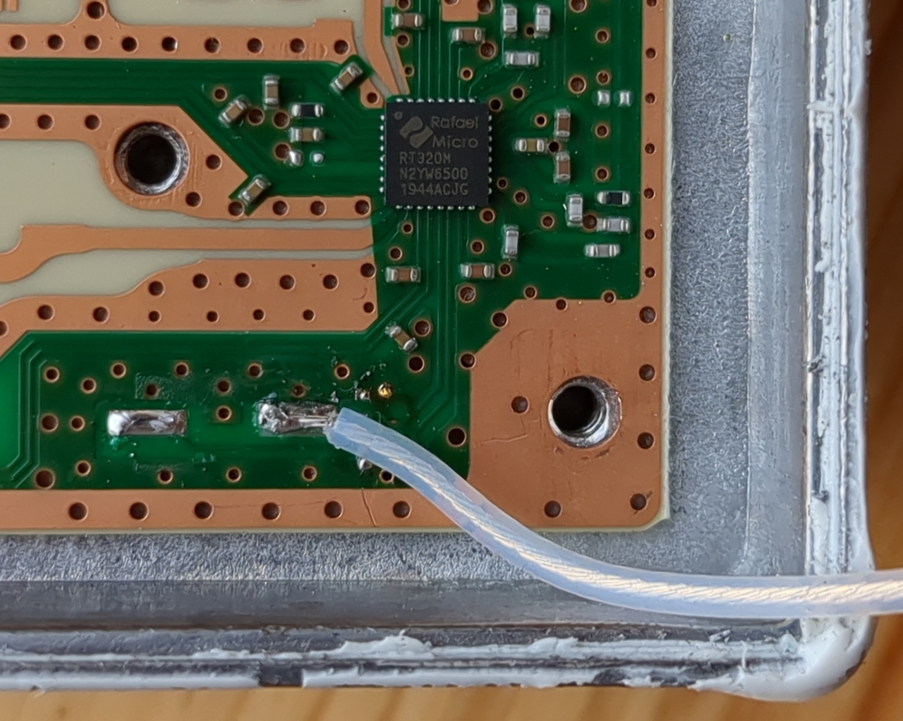
After removing the crystal and its capacitors, solder an insulated wire to the XTAL_IN pad:
The repurposed output port must be isolated from the LNB’s downconverted RF signal and from the DC supply path. Otherwise, the injected reference would be shunted by the LNB’s own output and power circuits. I cut the traces in two places marked red using a Dremel multi-tool.
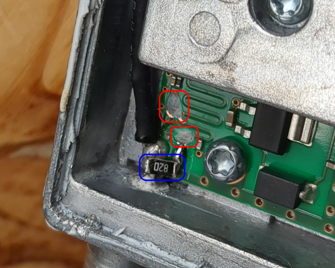
An 82 Ω resistor was soldered between the F connector pin and the PCB ground, directly at the connector, so the coax is terminated before the DC block.
A 100 pF capacitor connects the F connector pin to the wire going to XTAL_IN and is insulated with heat shrink tubing.
After the modification, the LNB is powered exclusively through the other F connector. Never apply the 13/18 V supply to the clock port. The 82 Ω resistor sits directly across it, so 18 V would make it dissipate about 4 W and burn it out.
Reference signal source
Any source producing a clean 25 MHz sine wave at the level given above (~0 dBm) will do: a TCXO, an OCXO, a GPS-disciplined oscillator for the best long-term stability or, for a quick test, a signal generator.
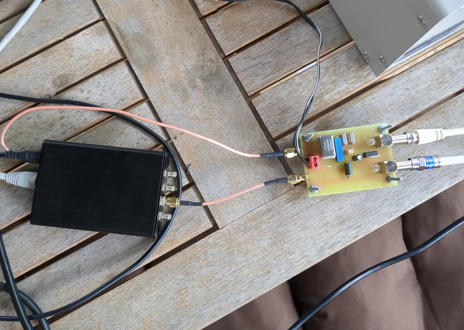
I made an experimental PCB that contains a stable VCTCXO with a two-crystal filter to produce a clean sine wave. In my setup, it provides the reference simultaneously to both the LNB and the Pluto+ SDR used as the uplink transmitter, so both are locked to the same clock. I’ll describe it in a follow-up article.
The reference frequency doesn’t have to be exactly 25 MHz: the LNB can be shifted to output directly in an amateur band, so that it works with an ordinary VHF/UHF transceiver instead of an SDR. With the RT320N’s multiplier of 390, the reference of 25.782 MHz puts the narrowband transponder at 70 cm (LO ≈ 10 055 MHz), and 26.526 MHz puts it at 2 m (LO ≈ 10 345 MHz). Since 1 kHz of reference offset moves the output by 390 kHz, the reference frequency must be set with at least this precision. I didn’t test this, though, and I don’t know whether the RT320N’s PLL can lock that far from its nominal frequency. Obviously, a 25 MHz crystal filter won’t pass such a reference either.