High voltage generator 1.0
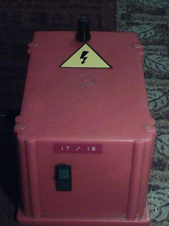
Warning
Working with high voltage can be lethal—disconnect power before starting and verify all wiring is correct and properly isolated before powering up.
This article is very old, from around 2006. It was originally published on my old website, slomkowski.glt.pl, now defunct. It’s unlikely to have much educational value. I’ve republished it mainly for sentimental reasons.
I’d like to describe a simple high voltage generator based on a car ignition coil. It’s a recreation of the generator described in the article Wytwórnia piorunów (“Lightning factory”), published in Elektronika dla Wszystkich 4/2002, a Polish hobby electronics magazine. The original PDF in Polish is available for download.
List of required components
| Part | Description |
|---|---|
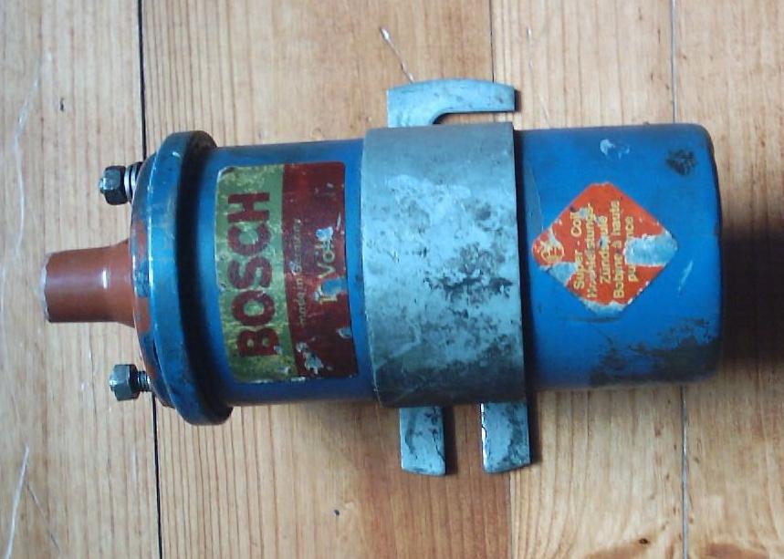
| Car ignition coil | Any ignition coil with a primary winding resistance of 1.5–4 Ω. |
| Power MOSFET transistor | It should have the drain-source resistance (RDS(on)) as low as possible, a drain current rating of several amperes, and UDS(max) of at least 500 V. I’ve used BUZ91A. |
| CMOS 4011 | |
| 2x low-power diode | For example, the popular 1N4148. |
| Resistors | 2x 4.7 kΩ, 1x 10 kΩ and 2x 100 kΩ potentiometers. |
| Capacitors | 1x 68 nF and an electrolytic 2200 μF 25 V. |
| Power supply | 12 V, capable of delivering a few amperes. |
| Other stuff | Prototyping board, wires, cables, and preferably some kind of enclosure. |
How to build it
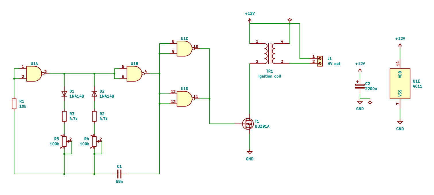
The oscillator is built from the logic gates U1A and U1B, together with C1, D1, D2 and
R1–R5. It generates a square wave with an adjustable duty cycle that drives the transistor T1 (gates
U1C and U1D are just buffers). Potentiometers R5 and R4 set the duration of the high and low states at
the output, respectively. The high state, during which the current in the coil builds up, shouldn’t last longer than 6–7 ms, otherwise the current grows
too large. With the values shown, it’s limited to about 5 ms. The diodes D1 and D2 separate the two paths, so each potentiometer
can be adjusted independently.
While the output is high, the transistor conducts and energy is pumped into the primary winding of the ignition coil. As soon as the output goes low, the transistor cuts off the current. This rapid shutoff induces 500–600 V of opposite polarity in the primary winding, and consequently over 20 kV in the secondary.
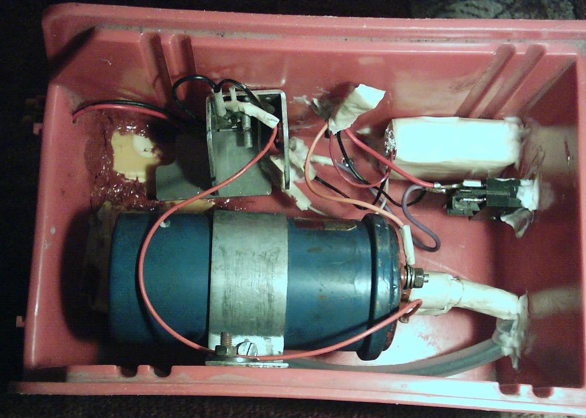
The generator can be assembled on a universal PCB, or even dead-bug style 🙂 Because of electromagnetic interference, the generator board should be separated from the power transistor and the coil: either placed at least 0.5 m away, or enclosed in a shielded box. I put mine in a matchbox wrapped in aluminum foil connected to ground.
The power MOSFET should have low drain-source resistance (RDS(on)), a drain current rating of several amperes, and UDS(max) of at least 500 V, because of the high voltage induced in the primary winding mentioned above. The lower the RDS(on), the less the transistor heats up. I used BUZ91A with a small radiator (see the photo above), which gets quite warm after two minutes. IRF840 has a similar RDS(on) and should work just as well. BUZ90A will work too, but its RDS(on) is higher, so it needs a larger radiator.
Running it
First, test the signal generator. Connect it to the 12 V power supply, then connect a piezo buzzer, a small speaker or headphones between ground and the output. There should be a high-pitched sound. Turning the potentiometers should make the sound vary.
Connect the power supply, the transistor and the coil with thick wires. It’s a good idea to make an enclosure for the device; I used a plastic drawer from a tool cabinet. Use HV cable to connect the high voltage output to the output terminal. Now you can adjust the potentiometers to get the biggest spark. Always switch the power off before touching anything, including the potentiometers. The high voltage pulses appear not only at the HV output, but also on the drain of the transistor.
Experiments
This article was never finished because the generator broke down during testing. Some time later, I used the working parts to build HVGen 2.0, which produces much more spectacular effects.