Experiments with microbial batteries
This article is very old, from around 2006. It was originally published on my old website, flylab.ovh.org, now defunct. It’s unlikely to have much educational value. I’ve republished it mainly for sentimental reasons.
I describe here how to build a galvanic cell. An unusual one though, as the electrolyte will be produced by living organisms such as bacteria and protozoa, the kind that inhabit puddles, lakes and similar waters. I built two versions, one sealed and another one with a gas vent.
The idea came from the 1974 edition of Nowoczesne zabawki (“Modern toys”) by Janusz Wojciechowski. This book has a kind of legendary status among the amateur tinkerers of the PRL era. I did not grow up in those times myself, but as an early teenager I was fascinated by its content after borrowing a copy from the local library. A great overview of the book and its cultural significance can be found in Adam Śmiałek’s video on YouTube. Also, some good soul scanned this book and published it on archive.org.
A scan of the fragment of the book concerning the microbial batteries:
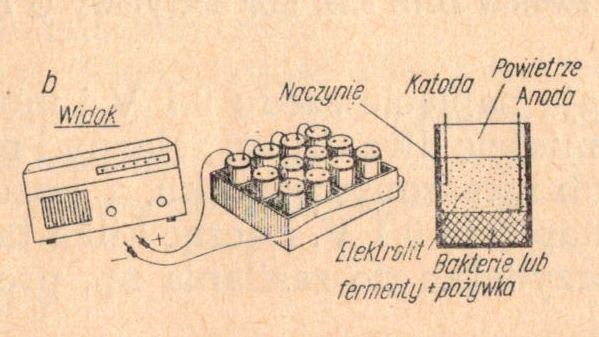
The biological battery (fig. 6-6b) consists of 12 cells in small plastic vessels (⌀ 50 x 100 mm) containing powdered rice husks along with the anodes and the cathodes. Harmless bacteria feeding on this medium produce, once water has been poured into the 12 vessels, a current of about 40 mA at a voltage of 6 V. The supply of the medium lasts for over half a year of continuous operation of the cell.
Like many others in this book, the claims about the performance of these cells are wildly exaggerated. Back then I didn’t know that. Anyway, building them was fun!
Tools required
Only common tools and ordinary kitchen utensils are required:
| Tool | Purpose |
|---|---|
| Coffee grinder | To grind the grain, preferably a hand-cranked one. |
| Kitchen utensils | To mix the growth medium. |
| Sandpaper | To clean the electrodes. |
| Soldering iron | To solder the lead wires to the electrodes. |
| Hot glue gun | To glue the electrodes in place and seal the cell. |
| Large syringe | To top the cell up with water. |
| Glass cutter | To cut the airlock down to length, only if a glass airlock is used. |
| Multimeter | To measure what the finished cell produces. |
Electrolyte
We are not really going to make the electrolyte, since the bacteria will produce it. All we do is prepare a suitable growth medium and living conditions for them.
| Ingredient | Comment |
|---|---|
| Rice or another grain | Three tablespoons per cell. |
| Grass | Any type of grass that grows on a porch, just a little bit. |
| Water containing living organisms | Half a glass is enough. |
Start by grinding the rice or another grain together with a few leaves of grass. A coffee grinder works best, but use one you no longer need for coffee — while being ground, the grass releases an intense smell and a juice that the grinder may absorb.
Now you need to add water containing the microbes. Water from a lake, a river, a puddle, or a garden rain barrel (which is what I used) will do. The most hardcore experimenters may use water from the toilet (just not right after cleaning it with bleach), which for obvious reasons I do not recommend, especially if the cell is being assembled in the kitchen.
Mix the water with the medium to obtain a thick pulp. Prepare the amount of pulp that will fill the cells up to 2/3.
First version of the cell
The drawing below shows a cross-section of the cell. Incidentally, this is my first piece of work made in a 3D graphics program (namely PovRay). The blue part is water, red and black are the voltage leads, gray and yellow are the aluminum/steel and copper electrodes, light yellow is the ground grain, and light red is the Tic Tac box.
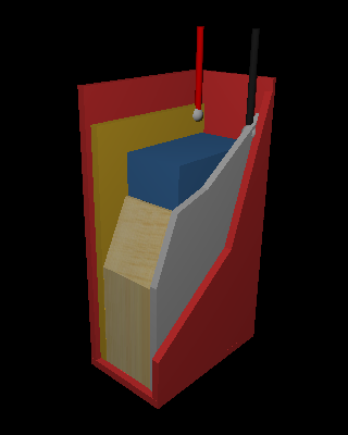
First, the enclosure of the cell has to be made, and a Tic Tac box will do. Cut the copper and the aluminum/steel sheet so that they fit loosely inside the box. Now clean them thoroughly with sandpaper. Note that aluminum is a poor choice for the electrode because it passivates — it covers itself with an insulating layer of aluminum oxide. Another issue is that aluminum is very hard to solder. Zinc or steel is a much better choice.
Next, solder the lead wires on, preferably in the top corner, and glue the electrodes to the inner walls of the box. It’s worth filling the area around the wire outlets with glue right away, and running a bead of glue around the inner rim of the box as well. This makes it much easier to seal the cell hermetically later on.
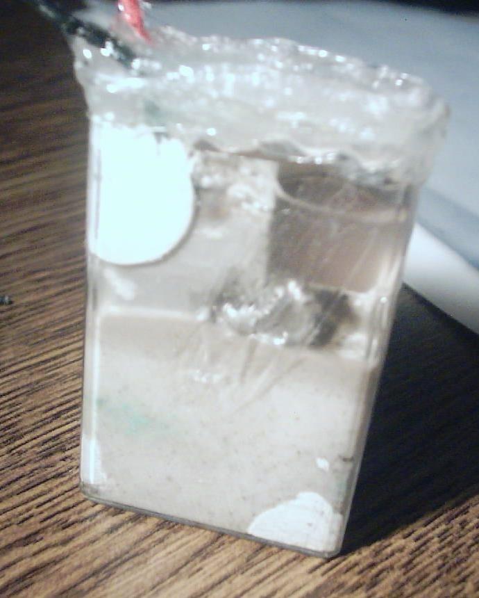
Fill the box with the pulp to about 2/3 of its height, then top it up with water (using the syringe) so that the water level is slightly below the points where the wires are soldered.
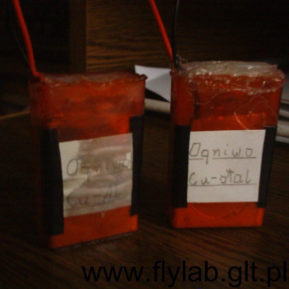
Now it’s time to seal the cell. This has to be done properly, because the bacteria produce a certain amount of gas — you can tell by the slightly bulging box. First, tear a rectangle of paper of a suitable size and lay it on the bead of glue made earlier. Now the opening can be filled with glue without any risk of the glue falling into the water. The cell is ready.
Materials
| Material | Details |
|---|---|
| Copper sheet | 40 x 30 mm, preferably 0.05 to 0.5 mm thick — having nothing else at hand, I used a sheet 2.5 mm thick (!). |
| Steel, zinc or aluminum sheet | Dimensions same as above. |
| Tic Tac box | The enclosure of the cell. |
| Wires | To carry the current out. |
Performance
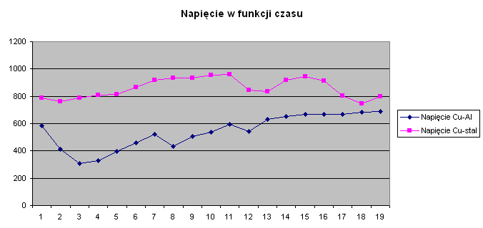
One should measure the voltages produced by the cells — mine were 790 mV for the copper-steel cell and 580 mV for the copper-aluminum one. That suggests that aluminum, despite having a highly negative standard electrode potential, is a rather poor choice for the electrode, for the reason given above.
Note that the cells become usable only after about two weeks — the microbes need time to grow and produce the electrolyte. I measured the voltage of both cells as a function of time. The chart is below. Unfortunately, I forgot to measure the current, so the available power cannot be determined. SparkFun has a nice description of how to measure a cell’s internal resistance and available power.
Second version of the cell
The first version of the cells produced a lot of internal pressure and eventually they started leaking, so I decided to build a second version and equip it with a fermentation lock. The drawing below shows a cross-section of the cell:
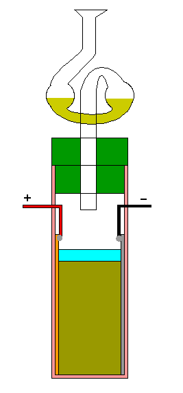
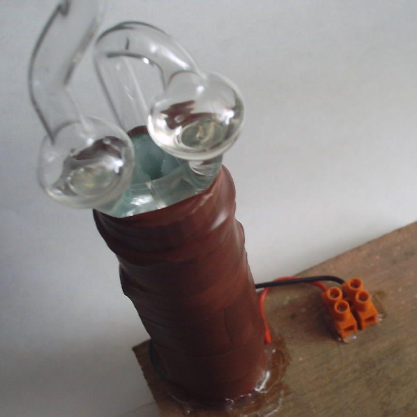
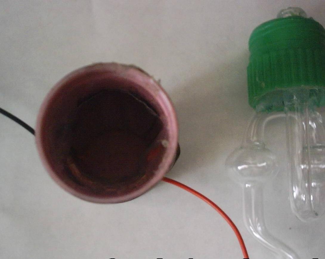
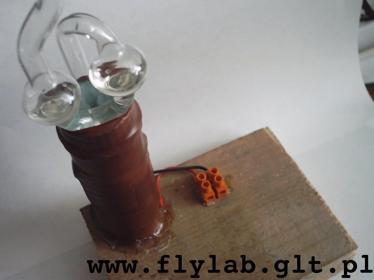
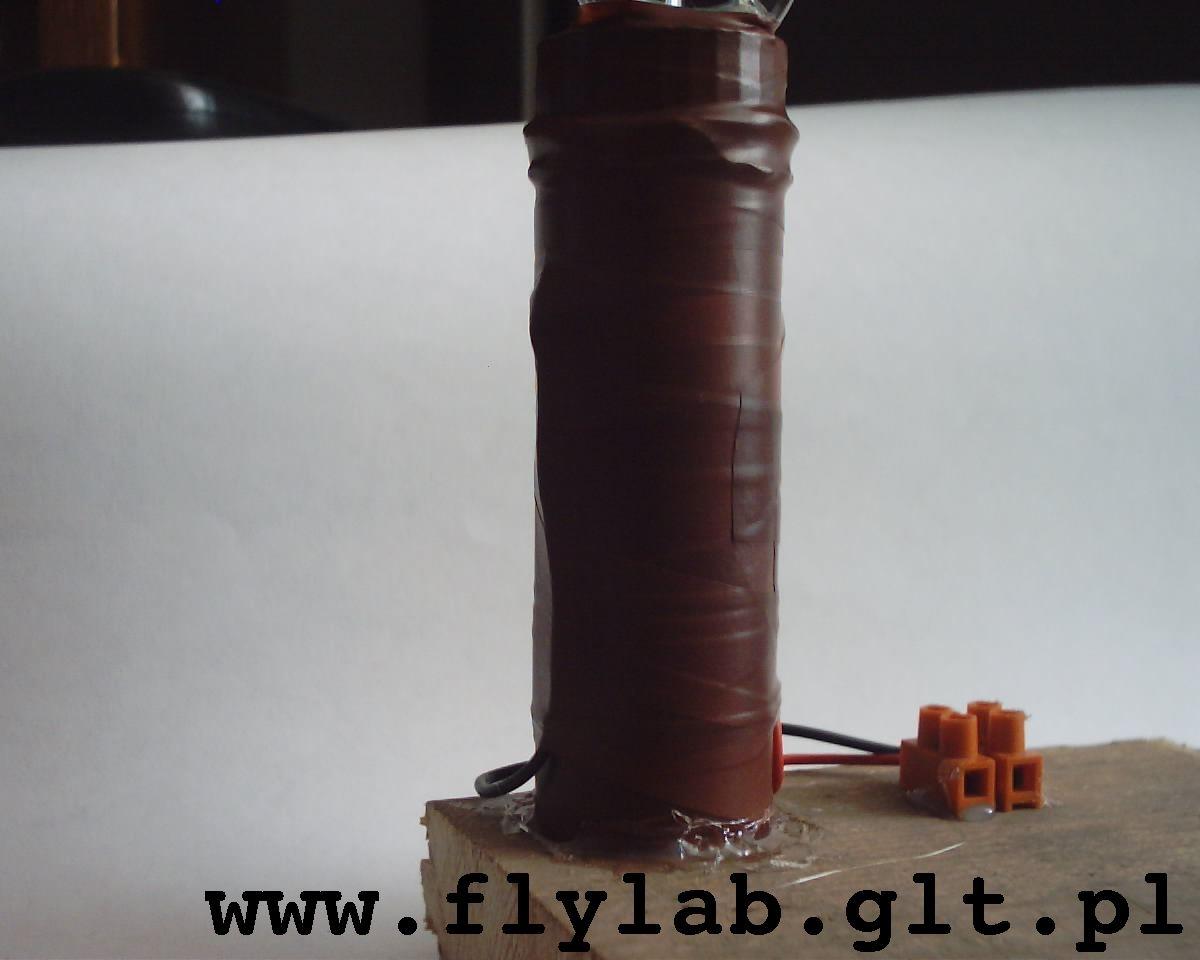
A plastic fermentation airlock is preferable, but a glass one will do as well. Cut the airlock down so that it is not too long — with the glass one you have to use a glass cutter, so be careful. Make a hole in the container’s cap so that the airlock can be pushed in, and seal the joint with hot glue. Prepare the electrodes and the connecting wires. The wires are led out through holes in the side wall of the container. Fill the container with the pulp to about 2/3 of its height, then top it up with water (using the syringe) so that the water level is slightly below the points where the wires are soldered. Screw the cap on and seal the joint with glue. Pour vegetable oil into the airlock, up to the level where its bulbs begin. The oil doesn’t evaporate and won’t let the smell out. Note that here, too, the cell becomes usable only after about two weeks.
Materials
| Material | Details |
|---|---|
| Copper sheet | 60 x 30 mm, preferably 0.05 to 0.5 mm thick — having nothing else at hand, I used a sheet 2.5 mm thick (!). |
| Steel or zinc sheet | Dimensions same as above. |
| Cylindrical container | I used one from a soap bubble toy. |
| Fermentation airlock | The kind used in winemaking, available in kitchenware shops. |
| Wires | To carry the current out. |
Applications
After about a month, my second version of the battery delivered around 10 mA when shorted out. Such batteries can be successfully used to power a watch or a small electronic circuit when several of them are put in series.
Additional information
The table below is an abbreviated electrochemical series of metals:
| Element | Symbol | Potential |
|---|---|---|
| Magnesium | Mg | -2.38 V |
| Aluminum | Al | -1.66 V |
| Zinc | Zn | -0.76 V |
| Iron | Fe | -0.44 V |
| Tin | Sn | -0.14 V |
| Lead | Pb | -0.13 V |
| Hydrogen | H | 0 V |
| Copper | Cu | +0.37 V |
| Silver | Ag | +0.8 V |
| Gold | Au | +1.42 V |
The electrodes should be made of metals as far apart in the table as possible — in this case gold and magnesium. Since these are hard to come by, I used a copper-aluminum pair in one cell and copper-steel in the other. Aluminum is unsuitable, of course, because of the passivation described earlier.